
Concrete anti-scour guide wall structure and construction method

A construction method and concrete technology, which is applied in the direction of basic structure engineering, excavation, breakwater, etc., can solve the problems of large amount of anti-seepage engineering, long construction period, and complicated procedures, so as to ensure the anti-scour effect, reduce the construction period, reduce the The effect of soil erosion

Pending Publication Date: 2019-09-10
CHINA NORTHWEST WATER CONSERVANCY & HYDROPOWER ENG CONSULTING
View PDF0 Cites 0 Cited by
  • Summary
  • Abstract
  • Description
  • Claims
  • Application Information

AI Technical Summary

Problems solved by technology

[0003] The purpose of the present invention is to provide a concrete anti-scouring guide wall structure and construction method to solve the problem that in the prior art, the use of cofferdam filling will narrow the channel, and the cofferdam protection and anti-seepage engineering quantity is large, the construction period is long, complex process issues

Method used


Image

  • Concrete anti-scour guide wall structure and construction method
  • Concrete anti-scour guide wall structure and construction method
  • Concrete anti-scour guide wall structure and construction method

Examples


Embodiment 1

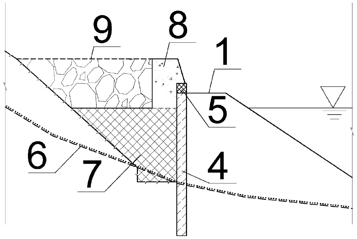
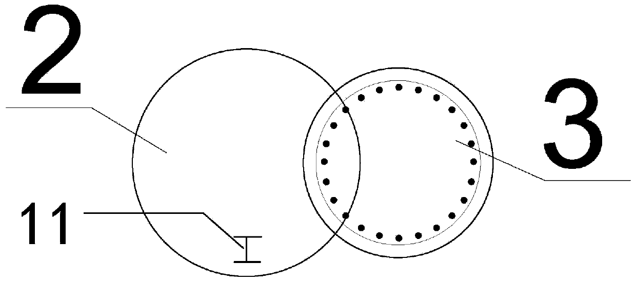
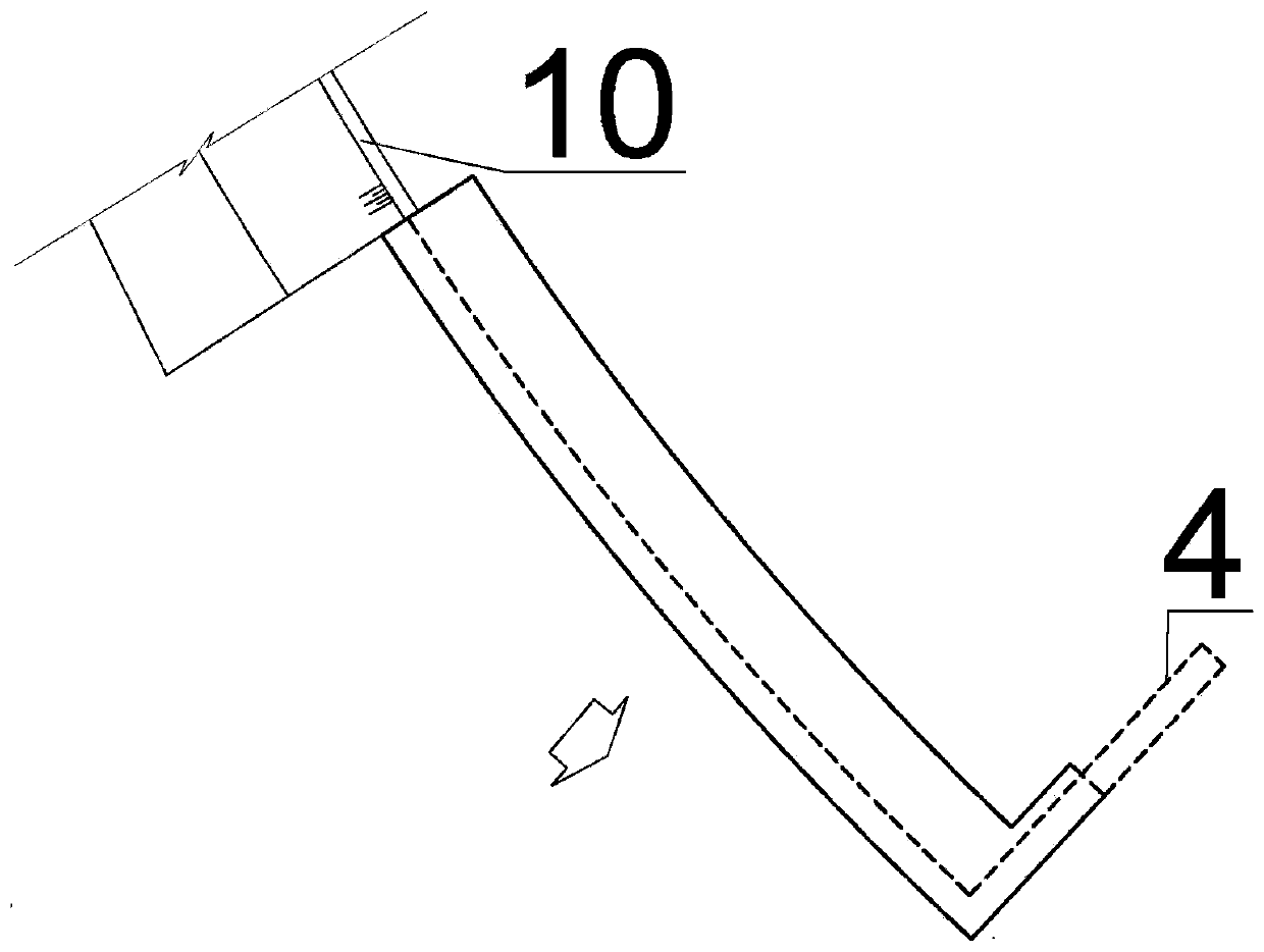
[0029] Such as Figure 1 to Figure 4 As shown, a concrete anti-scouring guide wall structure includes a construction platform 1, and the side of the construction platform 1 far away from the river is poured with an occlusal pile continuous wall 4, and a backfill pit is excavated behind the occlusal pile continuous wall 4, and the backfill pit is filled with There is a plain concrete layer 7, and the upper side of the plain concrete layer 7 close to the occlusal pile diaphragm wall 4 is poured with an upper guide wall structure concrete layer 8, and the part of the guide wall structure concrete 8 above the plain concrete layer 7 to the slope surface is paved with an access road 9 . The side of the construction platform 1 away from the river channel is drilled to the bottom of the bedrock roof line 6 by means of percussion drilling or other methods, and then the continuous wall 4 of occlusal piles is poured into it as a separation wall. The bottom layer of the backfill pit behin...

Embodiment 2

[0036] Such as Figure 1 to Figure 4 As shown, a construction method of a concrete anti-scouring guide wall structure includes the following steps. In the first step, the construction platform 1 is leveled, and the slope on the side of the river is first filled or excavated to be the construction platform 1; Fill or excavate the slope to form a construction platform 1 with an upper plane width of 5-8m, so that subsequent mechanical equipment can work on the construction platform 1.

[0037] In the second step, the occlusal pile diaphragm wall 4 is constructed, and the occlusal pile hole is constructed on the side of the construction platform 1 far away from the river, and the first-order concrete plain pile 2 is poured into the occlusal pile hole, and then the second-order reinforced concrete pile 3 is constructed, and the first-order concrete pile is constructed. The plain pile 2 and the second sequence reinforced concrete pile 3 form a closed continuous wall 4 of occlusal pi...


PUM


Abstract

The invention relates to a concrete anti-scour guide wall structure and a construction method. The concrete anti-scour guide wall structure comprises a construction platform, wherein a secant pile continuous wall is poured on the side, away from a riverway, of the construction platform, a backfill pit is excavated behind the secant pile continuous wall, the backfill pit is filled with a plain concrete layer, an upper guide wall structure concrete layer is poured on the side, close to the secant pile continuous wall, on the upper part of the plain concrete layer, and a passage road is laid in the part located between guide wall structure concrete on the upper part of the plain concrete layer and a slope surface. Through the secant pile continuous wall 4, no temporary cofferdam is needed anymore, so that permanent and temporary combination and pile and wall unification of the concrete anti-scour guide wall structure are realized, namely, the construction cost and the construction time of the temporary cofferdam are saved, the construction period is shortened, the flood risk in the construction period is reduced, and water and soil erosion is reduced.

Description

technical field [0001] The invention belongs to the technical field of anti-scour guide walls of water conservancy and hydropower projects, and in particular relates to a concrete anti-scour guide wall structure and a construction method. Background technique [0002] The anti-scour guide wall structure of water conservancy and hydropower projects, such as diversion, flood discharge building outlets, river bank revetment, etc., mostly adopts the cast-in-place concrete guide wall type. structure. In order to facilitate the construction of concrete guide walls, cofferdams are generally used to protect foundation pits, and earth-rock cofferdams also need to be treated with anti-seepage to form dry construction conditions. For rivers with deep overburden and narrow channels, if the earth-rock cofferdam method is adopted, there will be problems such as large narrowness of the channel bundle, large amount of cofferdam protection, anti-seepage engineering, deep foundation pit, dif...

Claims


Application Information

Patent Timeline
Patent Type & Authority Applications(China)
IPC IPC(8): E02B3/06E02D17/04
CPCE02B3/06E02D17/04E02B3/066
Inventor 康文军巨亚东董占辉王建
Owner CHINA NORTHWEST WATER CONSERVANCY & HYDROPOWER ENG CONSULTING
Learn More