Mine anchor roddrill carriage

A bolt drilling rig and anchoring technology, which is used in the installation of bolts, drilling equipment, mining equipment, etc., can solve the complex structure of the manipulator, affecting the movable range of the manipulator, the movement accuracy of the bearing strength, the cost of the manipulator, and the later maintenance. problems such as rising costs, etc., to achieve the effects of simple structure, low manufacturing cost and reasonable setting

Pending Publication Date: 2019-09-10
江西鑫通机械制造有限公司
View PDF0 Cites 3 Cited by
  • Summary
  • Abstract
  • Description
  • Claims
  • Application Information

AI Technical Summary

Problems solved by technology

Existing rock bolters generally use general-purpose conventional multi-joint manipulators, and corresponding drive cylinders are used on each joint to realize their respective movements, which makes the structure of the whole manipulator complex.
As a result, both the cost of the overall manipulator and the cost of post-maintenance have increased. At the same time, the more complex structure of the manipulator also affects the movable range, load-bearing strength, and movement accuracy of the manipulator.

Method used


Image

  • Mine anchor roddrill carriage
  • Mine anchor roddrill carriage
  • Mine anchor roddrill carriage

Examples


Embodiment 1

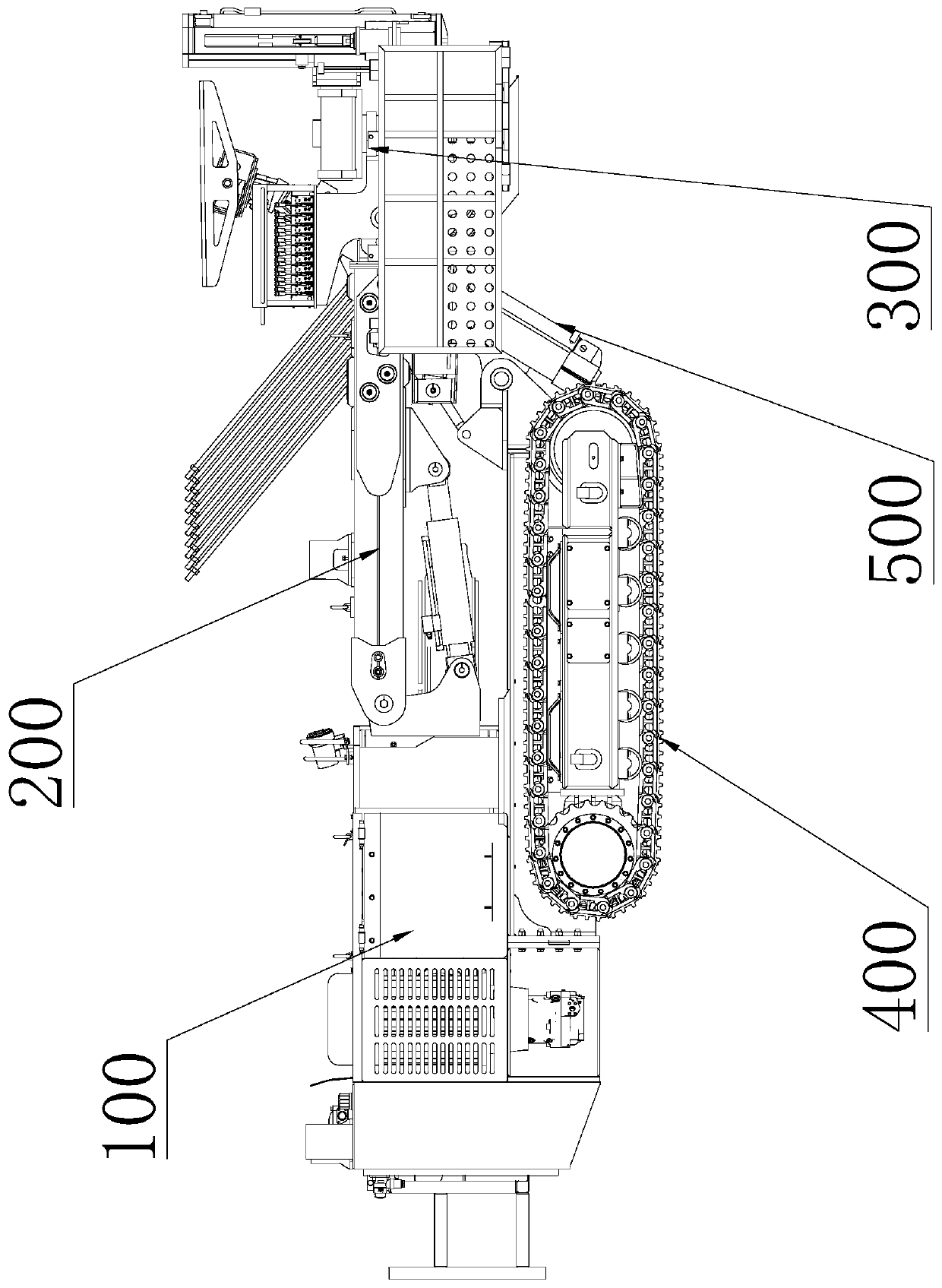
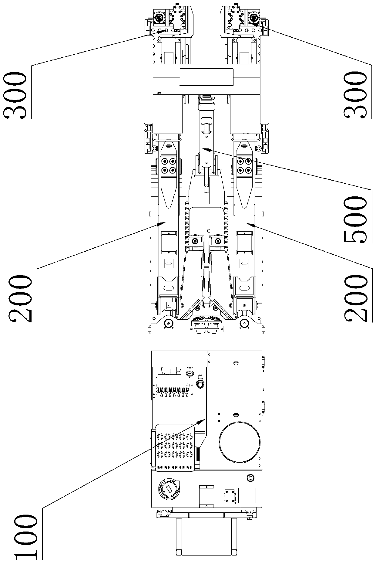
[0041] The basic structure is the same as the basic embodiment, the difference is that the present invention provides a novel mechanical arm, that is, a working arm 200 is provided, and the working arm 200 includes at least two sub-arms 7, as Figure 1-10 The two sub-arms 7 shown are taken as an example. The sub-arm 7 close to the body 100 is called the last sub-arm 7z, and the other sub-arm is called the first sub-arm 7a. The last One sub-arm 7z is a hollow structure, part of the first sub-arm 7a is inserted into the last sub-arm 7z, and the first sub-arm 7a and the last sub-arm 7z are slidably fitted along their own length. A telescopic cylinder 12 is provided in the last sub-arm 7z, and the telescopic cylinder 12 can adopt an air cylinder or various hydraulic cylinders. The rod body of the telescopic cylinder 12 is connected with the last sub-arm 7z, and the piston rod of the telescopic cylinder 12 is connected with the The last sub-arm 7z is connected, so that the relative...

Embodiment 2

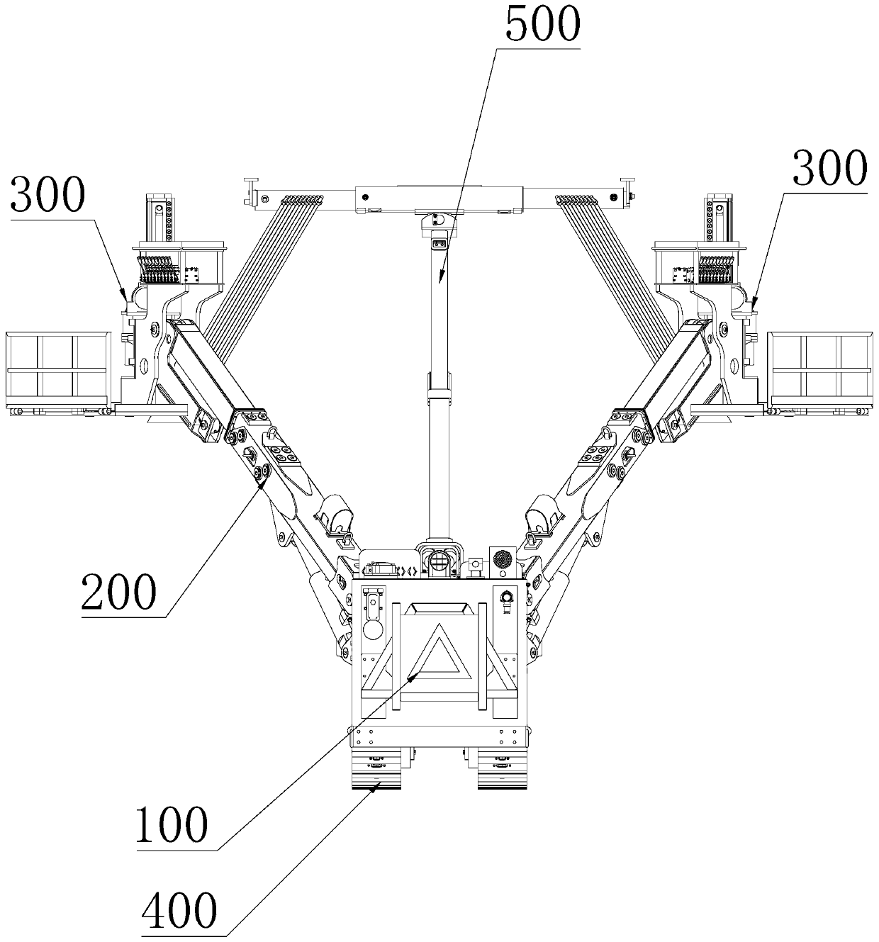
[0044] The basic structure is the same as that of Embodiment 1, the difference is: as Figure 6-9 The anchoring actuator shown includes a bearing base 1, the front end of the bearing base 1 is installed with a propulsion mechanism 2 for pushing the anchor rod, the rear end of the bearing base 1 is provided with a mounting part 1.1, and the bearing base 1 On both sides of the propulsion mechanism 2 are respectively provided with a working platform 3 and a bolt warehouse 4. The working platform is a platform for operators to stand and work, and the bolt warehouse 4 is an existing mechanism that can be used to store bolts, and the operator can place multiple bolts in the bolt warehouse 4 in advance , thereby facilitating the process of placing the anchor rods in the anchor rod bin 4 into the propulsion mechanism 2 one by one in the operation engineering to complete the anchoring process.

[0045] The propulsion mechanism 2 is used to drive the anchor rod into the area to be anch...

Embodiment 3

[0047] The basic structure is the same as that of the second embodiment, the difference is that: the upper end of the bearing seat 1 is provided with a batching bin 5 . The batching bin is used for storing other accessories and auxiliary materials except anchor rods.


PUM


Abstract

The invention discloses a mine anchor roddrill carriage which comprises a machine body and a walking mechanism. Themine anchor roddrill carriageis characterized in that at least one mechanical arm ismounted on the machine body, the mechanical arm comprises a working arm composed ofat least twosections of sub-arms, any adjacent twosections of sub-arms are slidably matchedin the length direction ofthe sub-arms, and the working arm is internally provided with a telescopic cylinder;an anchoring actuator is installed at the front end of the first-section sub-arm of the working arm, the front endof the first-section sub-arm is connected to abearing seat of the anchoring actuator through a mounting part, the anchoring actuator includes the bearing seat, anda propulsion mechanism is installed at the front end of the bearing seat; and the mounting part is installed at the rear end of the bearing seat, and working platforms and anchor rod bins are disposed at the positions, on the two sides of the propulsion mechanism, of the bearing seat correspondingly. According to the mine anchor roddrill carriage, the structure of the mechanical arm is simpler and more reliable, so that the cost of the whole vehicle is lower and the structure is more reliable.

Description

technical field [0001] The invention relates to the technical field of mining machinery, in particular to a mining rock bolter. Background technique [0002] The bolter is a self-moving device that drills bolt holes in the roof or side of the underground roadway and completes part or all of the bolt installation process. Existing rock bolters generally use general-purpose conventional multi-joint manipulators, and corresponding drive cylinders are used on each joint to realize their respective movements, thus making the structure of the whole manipulator complex. As a result, both the cost of the overall manipulator and the cost of post-maintenance have increased. At the same time, the more complex structure of the manipulator also affects the movable range, bearing strength, and movement accuracy of the manipulator. Contents of the invention [0003] The present invention aims to solve the first technical problem in the related art at least to a certain extent: to provid...

Claims


Application Information

Patent Timeline
Patent Type & Authority Applications(China)
IPC IPC(8): E21D20/00E21B7/02E21B15/00
CPCE21B7/02E21B15/00E21D20/003
Inventor 邹海波刘铭宇张泽王征峥张其智徐嘉麟孙崇君杨明张凤生王浩权
Owner 江西鑫通机械制造有限公司
Why Eureka
Try Eureka