
Vacuum and pressure test bench for full pipeline of braking system

A braking system and pressure testing technology, applied in the direction of using liquid/vacuum degree for liquid tightness measurement, fluid tightness test, machine/structural component testing, etc. , Unable to provide data support for filling process verification, unable to reflect the real vacuum and pressure status, etc., to facilitate real-time monitoring data, save parameter correction time, and avoid repeated testing.

Inactive Publication Date: 2019-09-10
DONGFENG MOTOR CORP HUBEI
View PDF7 Cites 3 Cited by
  • Summary
  • Abstract
  • Description
  • Claims
  • Application Information

AI Technical Summary

Problems solved by technology

[0005] Although the device disclosed in CN205328598U can detect the vacuum at the end of the braking system, filling pressure and gas content, it cannot reflect the overall real vacuum and pressure state of each pipeline of the braking system. The vacuum degree and filling pressure cannot provide data support for the previous filling process verification, and repeated measurements are required, which is time-consuming. In the mass production stage, there is no basis for diagnosing assembly abnormalities and component defects, which cannot be quickly Find out the bad sealing part of the brake system, the whole process is time-consuming and labor-intensive

Method used


Image

  • Vacuum and pressure test bench for full pipeline of braking system
  • Vacuum and pressure test bench for full pipeline of braking system
  • Vacuum and pressure test bench for full pipeline of braking system

Examples


Embodiment 1

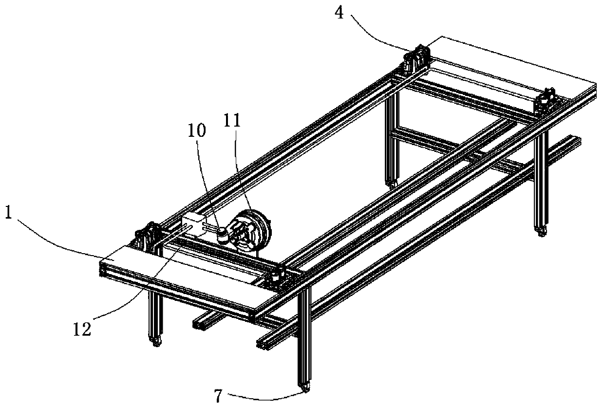
[0029] see figure 1 As shown, the embodiment of the present invention provides a vacuum and pressure test bench for the entire pipeline of the brake system, including a frame body 1, a collection device and a transmission device, and the frame body 1 is provided with a brake fluid pot 10, a booster Device 11 and pipeline system, the pipeline system is set on the frame body 1, the brake fluid pot 10 communicates with the pipeline system through the booster device 11, and the filling fluid filling equipment fills the filling fluid through the brake fluid pot 10 To the pipeline system; the collection device is set on the pipeline system, which is mainly used to collect the vacuum degree and pressure value of at least two points in the pipeline system, wherein one of the two points is located in the pipeline system far away from the booster device 11 One end of the pipeline system is the end of the pipeline system, and the other point is located on other connecting sections of the...

Embodiment 2

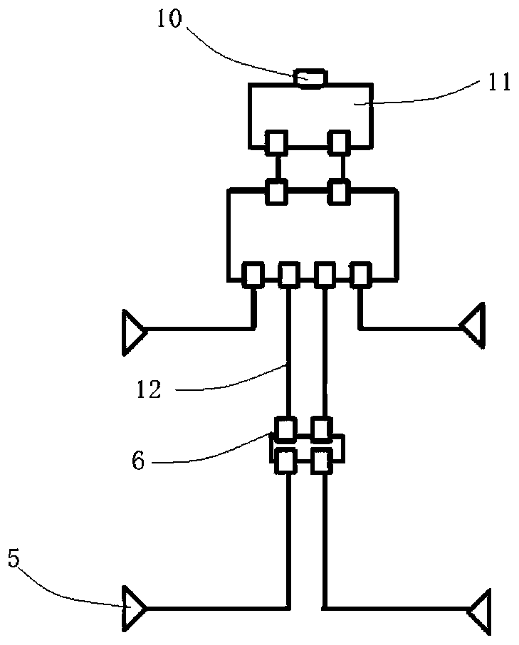
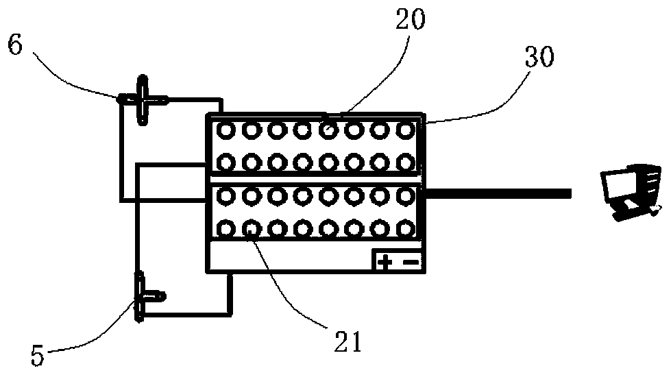
[0036] Basic content is the same as embodiment 1, and the difference with embodiment 1 is, see Figure 2-3 As shown, the piping system also includes a plurality of three-way valves 5 and four-way valves 6. The three-way valves 5 are used to communicate the pipeline 12 with the exhaust port and the vacuum sensor 20 and pressure sensor 21 located at the exhaust port. The valve 6 is used to connect the connections between the various pipelines 12 , and for the sake of equipment and cost saving, other vacuum sensors 20 and pressure sensors 21 except those arranged at the ends are respectively provided at the connection of every two adjacent pipelines 12 . Specifically, two ends of each four-way valve 6 are respectively connected to its adjacent pipeline 12, and the remaining two ends are respectively connected to a vacuum sensor 20 and a pressure sensor 21, and one end of each three-way valve 5 is connected to an exhaust The remaining two ends are connected to the vacuum sensor 20...

Embodiment 3

[0038] The basic content is the same as that of Embodiment 2, and the difference from Embodiment 2 is that the transmission device includes a data acquisition card 30, and the data acquisition card 30 is connected to the vacuum sensor 20 and the pressure sensor 21, and the data acquisition card 30 is used to transmit the vacuum collected. Degree and pressure value, and the collected vacuum degree and pressure value are transmitted to the computer which can be displayed and analyzed and processed, which is convenient for the operator to monitor the monitored data in real time, and is convenient for observation and analysis and processing.


PUM


Abstract

The present invention discloses a vacuum and pressure test bench for full pipelines of a braking system and relates to the field of automobile braking system testing. The device comprises: a frame body, a collecting device and a transmission device, wherein a brake fluid pot, a boosting device and a pipeline system are provided on the frame body, a pipeline system is disposed on the frame body, the brake fluid pot is in communication with the pipeline system through the boosting device, the collecting device is disposed on the pipeline system and is configured to collect vacuum degree and pressure values of at least two points of the pipeline system, and one of the two points is one end of the pipeline system away from the boosting device, and the transmission device is configured to receive the collected vacuum degree and the pressure values and to transmit. The vacuum and pressure test bench can detect the vacuum degree and the pressure values of all the pipelines of the braking system during a filling process, so as to obtain accurate vacuuming time and reasonable vacuum leak detection parameters, and at the same time provides testing and evaluation basis for subsequent mass production.

Description

technical field [0001] The invention relates to the field of automobile brake system testing, in particular to a vacuum and pressure test stand for the entire pipeline of the brake system. Background technique [0002] As a system to ensure the normal driving of the car, the braking system plays a vital role in the safety of personnel and the stable driving of the vehicle. With the improvement of people's requirements for car safety, the braking device of the car is also constantly improving and improving. The booster in the automobile braking device generally adopts a vacuum booster. Its principle is to use the pressure difference between the vacuum of the engine intake pipe and the atmosphere to play a boosting role. The vacuum booster includes a front cavity and a rear cavity. By controlling the front cavity and the rear cavity The communication state between the cavities and the vacuum value are used to control the film assembly to push the piston body forward, thereby p...

Claims


Application Information

Patent Timeline
Patent Type & Authority Applications(China)
IPC IPC(8): G01M3/28G01L11/00G01L21/00
CPCG01L11/00G01L21/00G01M3/2807G01M3/2815
Inventor 巩安周李金晶刘世涛江楠王守良
Owner DONGFENG MOTOR CORP HUBEI
Learn More