Method for analyzing swing high-speed jet characteristics of underwater engine nozzle

An engine nozzle, high-speed jet technology, applied in special data processing applications, instruments, electrical digital data processing and other directions, can solve problems such as increasing the complexity of the nozzle underwater high-speed jet

Active Publication Date: 2019-09-10
BEIJING INSTITUTE OF TECHNOLOGYGY
View PDF5 Cites 11 Cited by
  • Summary
  • Abstract
  • Description
  • Claims
  • Application Information

AI Technical Summary

Problems solved by technology

At the same time, in order to enable the missile to adjust its flight attitude and obtain more flexible maneuverability when navigating underwater, a thrust vector control device is essential, among which the swinging nozzle has been widely used as a high-efficiency thrust vector control method, and The swing of the nozzle will also greatly increase the complexity of the underwater high-speed jet of the nozzle
At present, there is no relatively accurate analysis method and numerical calculation method for the external flow field structure and thrust characteristics of the underwater nozzle swinging high-speed jet. It is necessary to study a numerical calculation method that can accurately simulate the flow characteristics of the nozzle swinging high-speed jet. Understand the principle of interaction between the water environment and gas when the engine works underwater, master the influence of the expansion ratio and water depth on the engine's operating characteristics, so as to provide a theoretical basis for reasonably predicting the engine's operating characteristics such as thrust value and noise

Method used


Image

  • Method for analyzing swing high-speed jet characteristics of underwater engine nozzle
  • Method for analyzing swing high-speed jet characteristics of underwater engine nozzle
  • Method for analyzing swing high-speed jet characteristics of underwater engine nozzle

Examples


Embodiment 1

[0052] In this embodiment, the nozzle structure used in the underwater nozzle supersonic gas jet experiment under normal temperature and low pressure conditions disclosed abroad is selected as the analysis object.

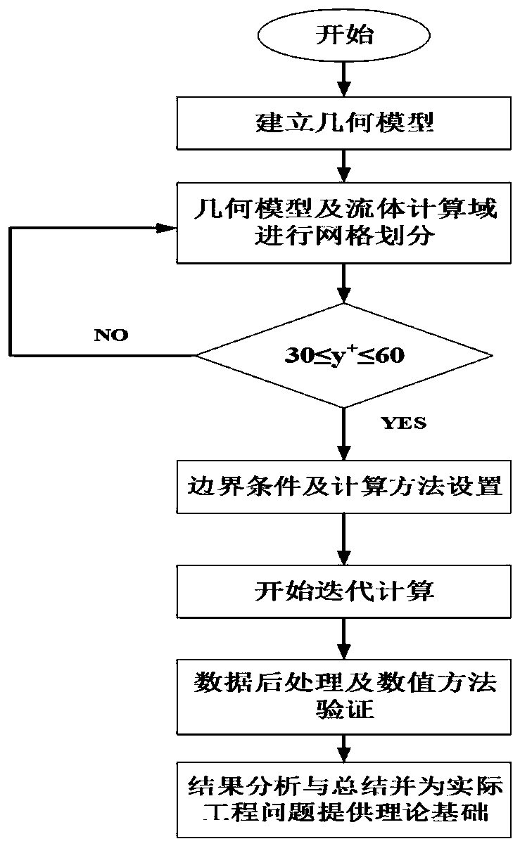
[0053] Such as figure 1 As shown, the analysis method for the flow characteristics of the underwater solid rocket motor nozzle swing high-speed jet disclosed in this embodiment, the specific implementation steps are as follows:

[0054] Step 1: Build a geometric model.

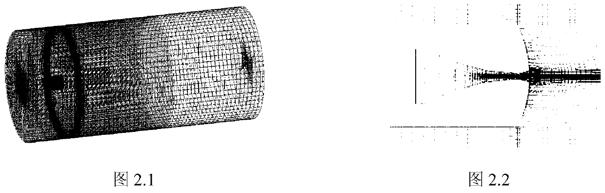
[0055] Taking the underwater solid rocket motor nozzle of the revolving body structure as the research object, the geometric parameters of the revolving body are determined, and the geometric modeling is carried out by using modeling software, as shown in figure 2 Shown is a schematic diagram of the geometric model of the underwater solid rocket motor nozzle used in the embodiment of the present invention.

[0056] The specific implementation method of step 2 includes the following steps:

[00...


PUM


Abstract

The invention discloses a method for analyzing swing high-speed jet characteristics of an underwater engine nozzle, and belongs to the field of fluid mechanical engineering. The implementation methodcomprises the following steps of: through establishing a geometric model of an underwater solid rocket engine nozzle, establishing a fluid calculation domain, carrying out geometric optimization on aninterface of the two fluid calculation domains, setting an interface between the calculation domains for data transmission to achieve simulation of the swing working condition of the nozzle, carryingout grid division on the fluid domains in a partitioned mode, carrying out grid independence verification, and obtaining the optimal grid number; importing the obtained final grid file into a FLUENTsolver, setting boundary conditions, an adopted calculation model and a calculation method, and carrying out solving; carrying out numerical simulation analysis and post-processing on a numerical calculation result. The rocket engine nozzle swing high-speed jet flow characteristic is accurately simulated and analyzed, the nozzle swing high-speed jet flow rule and mechanism can be easily disclosed,a theoretical basis is provided for the engine nozzle structure design of underwater powered missile launching, and the actual engineering application problem of underwater powered missile launchingis solved.

Description

technical field [0001] The invention belongs to the field of fluid mechanical engineering, and relates to an underwater solid rocket motor nozzle swing high-speed jet flow field structure and thrust characteristic analysis method, in particular to an underwater solid rocket motor nozzle swing high-speed jet based on secondary development of CFD software Analysis method of jet flow field structure and thrust characteristics. Background technique [0002] The launch of submarine-launched missiles can be divided into unpowered and powered launches. The use of powered missile launch technology can actively control the body of submarine-launched missiles, which can greatly improve its combat effectiveness. As the most convenient power source for underwater propulsion technology, solid rocket motors are currently the most effective power source for various strike-type submarine-launched weapons. preferred driving force. [0003] The high density ratio, high back pressure, and co...

Claims


Application Information

Patent Timeline
Patent Type & Authority Applications(China)
IPC IPC(8): G06F17/50
CPCG06F30/17G06F30/20
Inventor 黄彪李达钦田北晨张佳悦王国玉高德明
Owner BEIJING INSTITUTE OF TECHNOLOGYGY
Why Eureka
Try Eureka