
Unmanned aerial vehicle signal source positioning and control system

A technology of unmanned aerial vehicle and signal source, applied in satellite radio beacon positioning system, radio wave measurement system, interference to communication and other directions, which can solve the problem that the operator of dangerous unmanned aerial vehicle-flight control source ignores and breaks into the airport and military restricted areas, irregular flight activities, etc., to achieve the effect of short positioning time, small interference, and reduced interference

Inactive Publication Date: 2019-09-10
BEIHANG UNIV
View PDF3 Cites 5 Cited by
  • Summary
  • Abstract
  • Description
  • Claims
  • Application Information

AI Technical Summary

Problems solved by technology

Due to the lack of standards, most of the civilian small UAVs are not equipped with relevant air traffic control modules (such as ADS-B), and the flight activities are very irregular, relatively random and hidden, and the flight is not easy to be found
The activities of many small drones have not been declared through the normal procedures for flight plans, which are prone to illegal incidents such as interfering with civil aviation flights, breaking into airports and military restricted areas
[0004] Moreover, the existing UAV control system is mainly to detect and counter the target UAV, while the operator of the dangerous UAV—the flight control source is often ignored

Method used


Image

  • Unmanned aerial vehicle signal source positioning and control system
  • Unmanned aerial vehicle signal source positioning and control system
  • Unmanned aerial vehicle signal source positioning and control system

Examples


Embodiment Construction

[0041] The present invention will be further described below in conjunction with the accompanying drawings and specific embodiments.

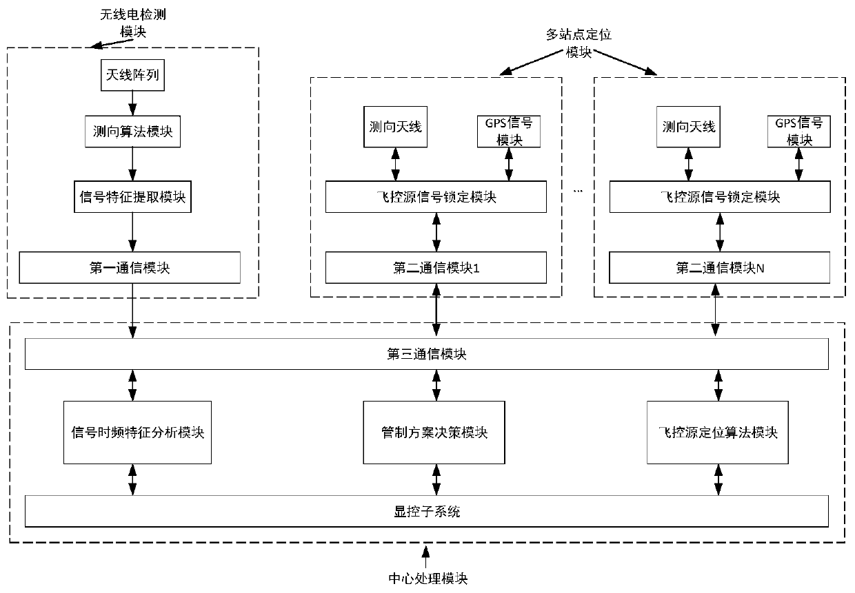
[0042] The invention provides a UAV signal source positioning and control system, which adopts the array antenna direction finding technology, and determines the specific position of the flight control source paired with the UAV through the coordinated direction finding of multiple array antenna direction finding stations , so that the relevant departments can take timely and effective measures to protect the safety of key areas, and realize the comprehensive control of UAVs in key areas. Compared with the traditional active radar direction finding method, the present invention adopts passive radio direction finding method, and has a direction finding station The advantages of low complexity, short time-consuming positioning, active detection, low cost, high positioning accuracy, little impact on the surrounding electromagnetic environment, low ...


PUM


Abstract

The invention discloses an unmanned aerial vehicle signal source positioning and control system, and belongs to the technical field of unmanned aerial vehicle control. The system comprises a radio detection module, a central processing module and N positioning stations. The radio detection module comprises an antenna array, a direction finding algorithm module, a signal feature extraction module and a first communication module; each positioning station comprises a direction finding antenna, a GPS signal module, a flight control source signal locking module and a second communication module. The central processing module comprises a signal time-frequency characteristic analysis module, a control scheme decision module, a flight control source positioning algorithm module, a display controlsubsystem and a third communication module. The radio detection module realizes signal transmission with the third communication module of the central processing module through the first communication module. The central processing module realizes bidirectional signal transmission with the second communication modules of the N positioning stations through the third communication module. The system has the advantages of small interference on the surrounding electromagnetic environment, short positioning time consumption and timely and rapid taking of control measures.

Description

technical field [0001] The invention belongs to the technical field of UAV management and control, and in particular relates to a UAV signal source positioning and control system. Background technique [0002] At present, unmanned aircraft systems have played an increasingly important role in national defense and economic construction, and the application requirements are constantly increasing. Due to the relatively low entry-level technical conditions and costs for R&D, manufacturing and use of UAS, domestic and foreign units and individuals are highly motivated to develop, manufacture, assemble and use UAS. Although this situation has promoted the development of the manufacture and application of unmanned aircraft systems, due to the large number of types of unmanned aircraft systems, different performances, and uneven technical levels, and there is currently no perfect unmanned aircraft system in my country. System management regulations, standards, technical means and la...

Claims


Application Information

Patent Timeline
IPC IPC(8): H04K3/00G01S19/48
CPCG01S19/48H04K3/80H04K2203/22
Inventor 张学军白琳王佳星
Owner BEIHANG UNIV
Learn More