Method for nondestructively detecting extended vertical depth of roll contact fatigue of steel rail

A technology of rolling contact fatigue and vertical depth, applied in the direction of electric/magnetic depth measurement, magnitude/direction of magnetic field, electromagnetic measuring device, etc., to achieve the effect of simple operation, good safety and convenient operation

Active Publication Date: 2019-09-13
GUILIN UNIVERSITY OF TECHNOLOGY
View PDF10 Cites 10 Cited by
  • Summary
  • Abstract
  • Description
  • Claims
  • Application Information

AI Technical Summary

Problems solved by technology

[0004] The existing AC electromagnetic field measurement method can only detect the surface length and pocket depth of cracks. For railway maintenance, rails need to

Method used


Image

  • Method for nondestructively detecting extended vertical depth of roll contact fatigue of steel rail
  • Method for nondestructively detecting extended vertical depth of roll contact fatigue of steel rail
  • Method for nondestructively detecting extended vertical depth of roll contact fatigue of steel rail

Examples


Embodiment 1

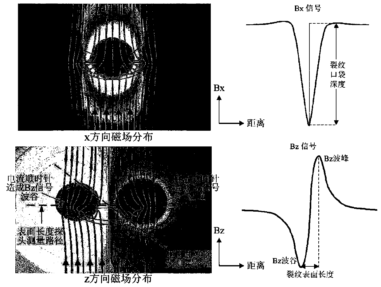
[0019] Under laboratory conditions, single cracks with different vertical depths are made on the rail by EDM, and AC electromagnetic field measurements are performed on the cracks according to steps 1 and 2 to obtain Bx and Bz signals, and the crack pocket depth, surface length and Bz are calculated The trough-to-peak ratio. Input the crack pocket depth, surface length and Bz trough-to-peak ratio in the finite element database established in steps 3 and 4 to obtain the vertical angle of the crack, and use trigonometric functions to calculate the vertical crack depth. The comparison between the finite element simulation and the actual measured Bz trough-to-peak ratio is shown in the appendix Figure 4 .

Embodiment 2

[0021] The difference between this application example and Example 1 is that the detection object is the rolling contact fatigue crack cluster in the actual rail (generally composed of multiple cracks with a distance of about 1-20 mm). Similarly, the finite element model is used to establish the crack cluster information database, and the longest vertical depth of cracks in the crack cluster is measured and judged, so as to completely remove the cracks. The AC electromagnetic field measuring probe scans the center point of the crack in a direction of 45° to the crack surface length to obtain the Bz trough-to-peak ratio, and input the data into the database to calculate the vertical angle of the crack. Combined with the pocket depth, the maximum vertical depth of the crack is calculated. The calculation results are compared with the actual results as shown in the table below:

[0022] Table 1 applies the method of the present invention to calculate the vertical depth of the cra...


PUM


Abstract

The invention discloses a method for nondestructively detecting the extended vertical depth of the roll contact fatigue of a steel rail. The method can solve the problem that during a steel tail maintenance and polishing process, the vertical depth of a crack is judged by experience or assumption, and provides quantitative theoretical analysis for the steel rail maintenance of a railway system, sothat the service life of the steel rail is prolonged, and the operation and maintenance costs of the railway are reduced. According to the method, based on an existing alternating current electromagnetic field measurement technology, a measurement probe needs to scan the crack by maintaining an included angle of 45 degrees with the length direction of the surface of the crack and pass through thecenter of the surface length of the crack, and thus a Bz signal is acquired, a Bz trough-peak ratio is computed, the relations between the ratios and actual crack vertical angles are researched, andthe vertical depth of the crack is computed in combination with a crack bag depth provided by a Bx signal. The relations between the cracks with different surfaces and vertical angles and the Bz trough-peak ratios are solved by using a finite element model and a database is built, and if the crack surface length and the Bz trough-peak ratio are input, the vertical depth of the crack can be output.

Description

technical field [0001] The invention relates to the fields of non-destructive flaw detection and rail transit, in particular to an electromagnetic non-destructive method for characterizing the vertical depth of rail rolling contact fatigue crack propagation. Background technique [0002] Rolling contact fatigue cracks are one of the typical surface defects of rails and wheels, which are caused by the repeated lateral and longitudinal traction of rails and wheels. Rolling contact fatigue cracks usually propagate toward the inside of the rail at an angle of 10-30° to the horizontal (vertical angle) (attached figure 1 ), when the crack growth reaches the fatigue limit, the crack will rapidly expand to the inside of the rail at a large vertical angle, causing the rail to break and easily causing a train derailment accident. From the perspective of rail maintenance, it is necessary to grind the rails regularly to eliminate the cracks before they reach the limit depth. The prere...

Claims


Application Information

Patent Timeline
IPC IPC(8): G01B7/26G01R33/02
CPCG01B7/26G01R33/02
Inventor 申嘉龙周磊刘军孟征兵李义兵
Owner GUILIN UNIVERSITY OF TECHNOLOGY
Why Eureka
Try Eureka