Piezoelectric vibration energy collection system capable of tracing maximum power point

A technology of maximum power point and piezoelectric vibration, applied in the direction of output power conversion device, piezoelectric effect/electrostrictive or magnetostrictive motor, adjusting electric variable, etc., can solve the problem that the maximum output power of energy extraction circuit is limited Issues such as output power, load dependence, and low efficiency of piezoelectric vibration energy harvesting

Active Publication Date: 2019-09-13
NINGBO UNIV
View PDF4 Cites 8 Cited by
  • Summary
  • Abstract
  • Description
  • Claims
  • Application Information

AI Technical Summary

Problems solved by technology

These two piezoelectric vibration energy extraction circuits based on maximum power point tracking did solve the problems of load dependence and load mismatch. However, they both first used a full-bridge rectifier circuit to rectify the output AC of the piezoelectric transducer, and then Then c...

Method used


Image

  • Piezoelectric vibration energy collection system capable of tracing maximum power point
  • Piezoelectric vibration energy collection system capable of tracing maximum power point
  • Piezoelectric vibration energy collection system capable of tracing maximum power point

Examples


Embodiment 1

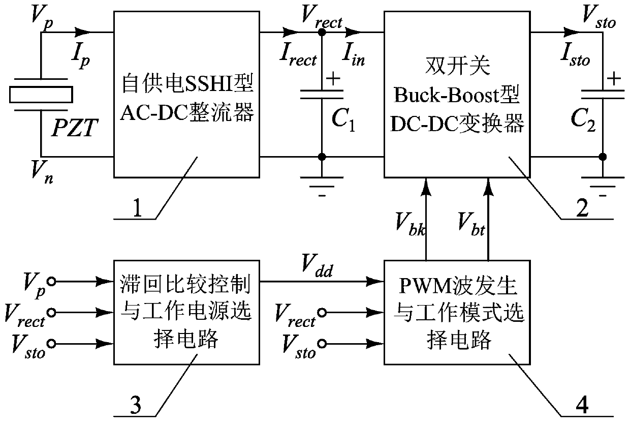
[0019] The present invention will be further described in detail below in conjunction with the accompanying drawings and embodiments. Embodiment one: if figure 1 As shown, a piezoelectric vibration energy harvesting system capable of tracking the maximum power point, including a piezoelectric transducer PZT and an electric energy extraction circuit, the piezoelectric transducer PZT is used to capture vibration energy and convert the vibration energy into AC output, The power extraction circuit includes self-powered SSHI AC-DC rectifier 1, double-switch Buck-Boost DC-DC converter 2, hysteresis comparison control and working power selection circuit 3, PWM wave generation and working mode selection circuit 4, the first The capacitor C1 and the second capacitor C2, the first capacitor C1 and the second capacitor C2 are both electrolytic capacitors, and the double-switch Buck-Boost type DC-DC converter 2 has two working modes: Buck step-down operation mode and Boost step-up operati...

Embodiment 2

[0020] Embodiment two: this embodiment is basically the same as embodiment one, the difference is as follows:

[0021] Such as figure 1 As shown, in this embodiment, the piezoelectric transducer PZT has a first output terminal and a second output terminal, and the self-powered SSHI type AC-DC rectifier 1 has a first input terminal, a second input terminal, an output terminal and a ground terminal , the double-switch Buck-Boost DC-DC converter 2 has an input terminal, a first control terminal, a second control terminal, an output terminal and a ground terminal, and the hysteresis comparison control and working power supply selection circuit 3 has a first input terminal, a second control terminal, and a ground terminal. Two input terminals, a third input terminal and an output terminal, the PWM wave generation and operation mode selection circuit 4 has a power supply terminal, a first input terminal, a second input terminal, a first output terminal and a second output terminal, ...


PUM


Abstract

The invention discloses a piezoelectric vibration energy collection system capable of tracing maximum power point. In the piezoelectric vibration energy collection system, a self-power supply SSHI-type AC-DC rectifier is used for converting an alternating current output from a piezoelectric transducer into a direct current, the direct current is output to a first capacitor, a hysteresis comparisoncontrol and working power supply selection circuit is used for controlling whether a PWM wave generation and working mode selection circuit enters a working condition or not, the PWM wave generationand working mode selection circuit is used for controlling a working mode of the dual-switch Buck-Boost type DC-DC converter, the first capacitor is controlled to be discharged when the dual-switch Buck-Boost type DC-DC converter enters the working condition, a second capacitor is charged, a voltage loaded onto the first capacitor is maintained around an optimal value, and tracing of maximum powerpoint is achieved. The piezoelectric vibration energy collection system has the advantage of relatively high vibration energy collection efficiency.

Description

technical field [0001] The invention relates to a piezoelectric vibration energy collection system, in particular to a piezoelectric vibration energy collection system capable of tracking the maximum power point. Background technique [0002] Mechanical vibration widely exists in the natural environment and human activities, and is a typical form of energy. The piezoelectric vibration energy harvesting system can capture the vibration energy generated by mechanical vibration, and finally convert the vibration energy into direct current that can be used by microelectronic devices for storage. The existing piezoelectric vibration energy harvesting system usually includes two parts: a piezoelectric transducer and an electric energy extraction circuit. The alternating current output by the energy converter is converted into direct current for storage. The piezoelectric transducer is a conventional device at present. After the piezoelectric transducer is determined, the perform...

Claims


Application Information

Patent Timeline
IPC IPC(8): H02N2/18H02M3/158G05F1/67
CPCG05F1/67H02M3/1582H02N2/181
Inventor 夏桦康夏银水叶益迭王健钱利波
Owner NINGBO UNIV
Why Eureka
Try Eureka