Thermal energy power supply driving device

A driving device and thermal energy technology, which is applied in the direction of circuit devices, battery circuit devices, electric vehicles, etc., can solve the problems of low heat dissipation rate, high cost, complex processing, etc., and achieve the effect of improving work efficiency, improving efficiency, and increasing cooling speed

Pending Publication Date: 2019-09-17
HUBEI SPORT MAN CUP POT MFG CO LTD
View PDF3 Cites 0 Cited by
  • Summary
  • Abstract
  • Description
  • Claims
  • Application Information

AI Technical Summary

Problems solved by technology

[0002] The existing public stirring cups, magnetic stirring cups, and magnetized cups are all driven by a single electric power supply, and need to be replaced or charged before use, resulting in high cost
[0003] There are many problems in the existing disclosed CN201520466866.1 thermally driven stirring cup. In this invention, the power generation device is arranged in the interlayer of the side wall of the cup body. The interlayer space of the side wall of the cup body is narrow and difficult to fix and implement;
[0004] In the existing disclosed CN201721409266.7 hot water automatic stirring cup and CN201721656172.X self-cleaning magnetic stirring cup, one side of the power generation piece is connected to the bottom outer surface of the inner tank, and the other side of the power generation piece is connected to the upper surface of the bottom cover of the metal cup , the bottom cover of the cup is made of aluminum alloy casting, and there are several vertically arranged metal heat sinks inside the bottom cover of the cup. The invention is to dissipate heat from the bottom surface of the power generation piece after the bottom surface of the power generation piece contacts the upper surface of the metal cup bottom cover. , not only lead to low heat dissipation rate, but also high cost of invention and manufacturing, complicated processing, which is not conducive to wide application and mass implementation

Method used


Image

  • Thermal energy power supply driving device
  • Thermal energy power supply driving device
  • Thermal energy power supply driving device

Examples


Embodiment Construction

[0043] The following will clearly and completely describe the technical solutions in the embodiments of the present invention with reference to the accompanying drawings in the embodiments of the present invention. Obviously, the described embodiments are only some, not all, embodiments of the present invention. Based on the embodiments of the present invention, all other embodiments obtained by persons of ordinary skill in the art without making creative efforts belong to the protection scope of the present invention.

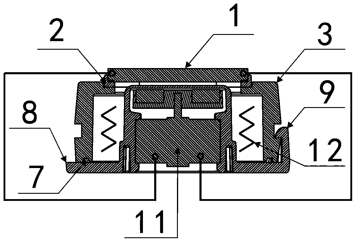
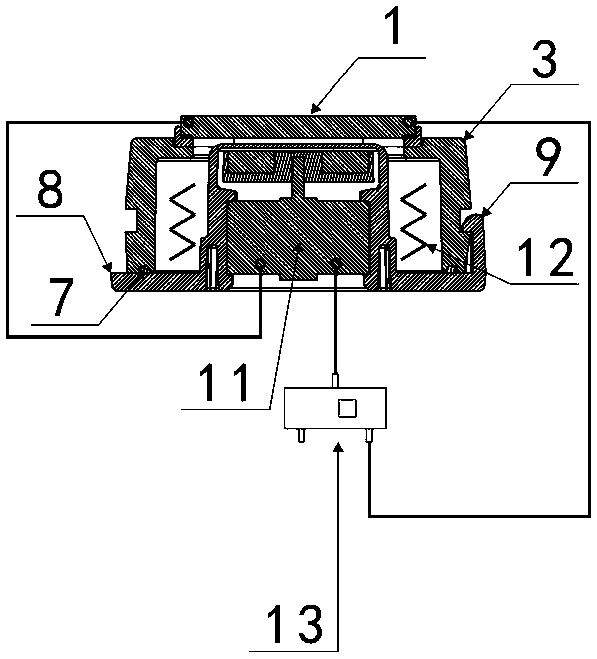
[0044] The invention provides a driving device powered by heat energy, which can improve the heat dissipation efficiency of the bottom surface of the generating sheet, thereby rapidly converting heat energy into electric energy and improving the working efficiency of the driver.

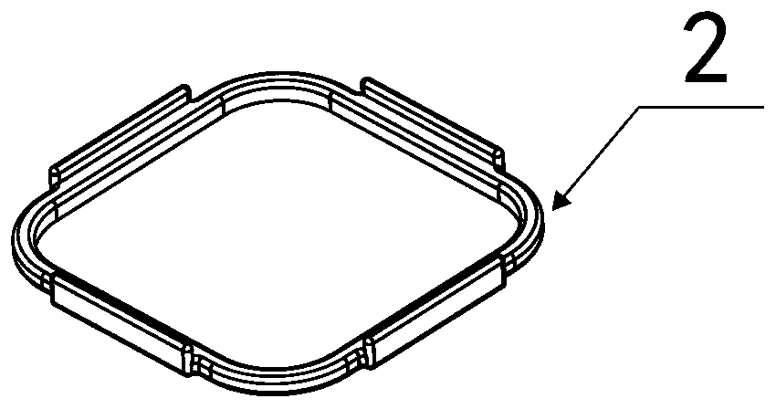
[0045] The embodiment of the present invention discloses a thermal power supply driving device, which includes a power generation chip 1, a silicone pad 2, a cooling liquid accommodat...


PUM


Abstract

The invention discloses a thermal energy power supply driving device. A cooling liquid accommodating cavity is of a transparent structure with an upper opening and a lower opening, and the lower opening of the cooling liquid accommodating cavity is matched with a silicone ring pressed by a bottom cover; the upper opening of the cooling liquid accommodating cavity is matched with a silicone pad pressed by a power generating piece; the cooling liquid accommodating cavity, the power generating piece and the bottom cover of the thermal energy power supply driving device are tightly matched to prevent leakage of cooling liquid; a cavity boss is arranged on the middle part of the bottom cover, and a drive is fixed into the cavity boss; the cooling liquid is injected into the cooling liquid accommodating cavity, and the power generating piece is electrically connected to the drive through a power line; and an upper plane of the power generating piece is in contact with a heat source body, and a lower plane of the power generating piece is in contact with the cooling liquid. The thermal energy power supply driving device can improve the heat dissipation efficiency on the bottom surface of the power generating piece, thereby forming a relatively high temperature difference between the upper plane and the lower plane of the power generating piece and then rapidly converting thermal energy into electric energy to improve the work efficiency of the drive.

Description

technical field [0001] The invention relates to the technical field of stirring cups, and more specifically relates to a heat-powered drive device for stirring cups. Background technique [0002] The existing public stirring cups, magnetic stirring cups, and magnetized cups are all driven by a single electric power supply, and need to be replaced or charged before they can be used, resulting in higher costs. [0003] There are many problems in the existing disclosed CN201520466866.1 thermally driven stirring cup. In this invention, the power generation device is arranged in the interlayer of the side wall of the cup body. The interlayer space of the side wall of the cup body is narrow and difficult to fix and implement; [0004] In the existing disclosed CN201721409266.7 hot water automatic stirring cup and CN201721656172.X self-cleaning magnetic stirring cup, one side of the power generation piece is connected to the bottom outer surface of the inner tank, and the other sid...

Claims


Application Information

Patent Timeline
Patent Type & Authority Applications(China)
IPC IPC(8): A47G19/22H02J7/32H02N11/00
CPCA47G19/2205H02J7/32H02N11/002
Inventor 冯志平
Owner HUBEI SPORT MAN CUP POT MFG CO LTD
Why Eureka
Try Eureka