Supercharge Your Innovation With Domain-Expert AI Agents!

Stamping processing method and processing mold for fuel tank connecting insert

A technology of stamping processing and fuel tank, which is applied in the direction of forming tools, manufacturing tools, metal processing equipment, etc., can solve the problems of local stress concentration, easy fatigue fracture, tearing, etc., to avoid mutual adverse effects, avoid local tearing, The effect of high production efficiency

Active Publication Date: 2021-04-13
JIANGSU SCHUERHOLZ PRECISION METAL FORMING CO LTD
View PDF6 Cites 0 Cited by
  • Summary
  • Abstract
  • Description
  • Claims
  • Application Information

AI Technical Summary

Problems solved by technology

Its disadvantage is that due to the existence of the inner flange, there is a circular arc transition area between the body and the inner flange during the flange processing, so that the inner position of the radial rib cannot be too close to the arc transition area. There is interference in the process between the two. If the radial rib is processed first, it is easy to cause local stress concentration and tearing when flanging; if the flanging is processed first, the radial rib is stamped. In this process, the inner circle side after flanging will be deformed; when the two are processed at the same time, there will be no interference only when they are far away from each other, otherwise the part will always have a certain degree of deformation
However, when the radial rib is far away from the arc transition zone, there is no reinforcing structure in the entire circumferential direction between the end of the radial rib and the arc transition zone, forming a weak link. Under working conditions, this position is prone to fatigue and fracture. In addition, under extreme conditions of impact, this position is more likely to tear, causing fuel leakage and even greater accidents

Method used


Image

  • Stamping processing method and processing mold for fuel tank connecting insert
  • Stamping processing method and processing mold for fuel tank connecting insert
  • Stamping processing method and processing mold for fuel tank connecting insert

Examples


Embodiment Construction

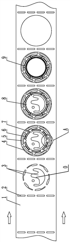
[0031] Such as Figure 1~3 As shown, it is a stamping method for a fuel tank connection insert, which includes the following steps:

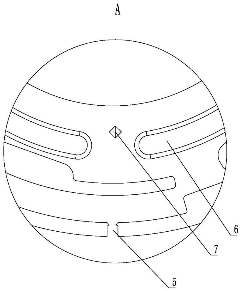
[0032] 1) Uncoil, level and pull the coiled material strip 1 into a stamping machine equipped with a progressive die. The material strip 1 moves in one direction in a step-by-step manner, and moves one station each time it moves; the progressive die contains at least Five stations; material strip 1 has a virtual center O for determining the circumferential direction and the radial direction on each station, and the virtual center O is used as the reference point in the circumferential direction and the radial direction, The circumferential direction is the circumferential direction of a circle drawn with the virtual center O as the center, the circle can also be virtual, and the radial direction is the radius or diameter direction of the circle corresponding to the virtual center O as the center.

[0033] 2) Along the traveling direction of the...


PUM

PropertyMeasurementUnit
thicknessaaaaaaaaaa

Abstract

The invention discloses a stamping processing method and a processing mold for a fuel tank connecting insert. In the method, a progressive die with five stations is used to process stress-relief holes at the first station; Through holes; at the third station, the circumferential reinforcing ribs, outer ring holes and pyramid grooves are simultaneously punched out by the third die; at the fourth station, the radial reinforcing ribs are punched out by the fourth die; at the fifth station, Punch out the inner flanging on the whole circumference of the center of the strip, and after the inner flanging is formed, the fifth mold will cut off the micro-connection. The processing mold matches and corresponds to it. The invention can be used for continuous production of fuel tank connecting inserts and has high production efficiency. The radial reinforcing ribs on the body of the insert can be extended to directly connect with the arc transition surface of the inner flanging, so as to improve the strength of the connecting insert.

Description

technical field [0001] The invention relates to a connection insert of a fuel tank, in particular to a continuous processing method and a processing mold for the connection insert of a fuel tank. Background technique [0002] At present, most of the fuel tanks of automobiles are made of plastic. In order to install oil pumps or other control valves, they need to be strengthened locally. Therefore, an insert is used, which is made of sheet metal. Its main structure It includes a disc-shaped body with an inner flange in the center of the body, and an insert hole that runs through the body is punched out on the body. When the fuel tank is injected, the insert hole is filled with plastic melt, and a stable structure is formed after solidification; In order to ensure that the insert itself has sufficient strength, the insert is stamped with circumferential reinforcement ribs and radial reinforcement ribs, the circumferential reinforcement ribs are intermittently arranged along th...

Claims


Application Information

Patent Timeline
Patent Type & Authority Patents(China)
IPC IPC(8): B21D35/00B21D37/08
CPCB21D35/001B21D37/08
Inventor 叶文慧张正国李伟张宇秋杨旭静姜潮李茂君韦凯
Owner JIANGSU SCHUERHOLZ PRECISION METAL FORMING CO LTD
Features
  • R&D
  • Intellectual Property
  • Life Sciences
  • Materials
  • Tech Scout
  • Unparalleled Data Quality
  • Higher Quality Content
  • 60% Fewer Hallucinations
Learn More