
Centrifugal concrete pile mold and flat car for shelving centrifugal concrete pile mold

A technology of concrete piles and moulds, applied in moulds, manufacturing tools, reinforced molding, etc., can solve the problems of not being on the same axis, unbalanced production capacity, and increased workload of cranes across workshops, so as to ensure position accuracy and facilitate cooperation Modeling and Optimizing the Effect of Centrifugal Concrete Pile Production Line

Pending Publication Date: 2019-09-17
俞晓东
View PDF3 Cites 5 Cited by
  • Summary
  • Abstract
  • Description
  • Claims
  • Application Information

AI Technical Summary

Problems solved by technology

[0004] The fed and prestressed and stretched molds need to be hoisted horizontally to the centrifuge by a crane. The process of the mold on the assembly line is to move the mold from one operation point to another by the crane. When running between two-span factory buildings When it is used, it is mainly transported by trolley, that is, the mold is hoisted onto the trolley by a crane, and when it reaches another cross-factory, it is hoisted from the trolley to the work site. There are many control procedures, and the centrifuge and the trolley transportation line are not in the same On the axis, it must be misaligned, resulting in an increase in space. With the additional increase in space, it will also cause unreasonable and difficult layout of other related processes. For example, the length of the workshop will be extended, and the corresponding other related to the workshop Workshop procedures also need to be adjusted, so that the entire process layout is not compact, which also increases the workload of the cross-factory crane and causes work conflicts between multiple cranes
As a result, the production capacity of the processes in the multi-span workshop is unbalanced, and there is a waiting phenomenon in some operations, which is not convenient for the automation and intelligence of the centrifuge process.

Method used


Image

  • Centrifugal concrete pile mold and flat car for shelving centrifugal concrete pile mold
  • Centrifugal concrete pile mold and flat car for shelving centrifugal concrete pile mold
  • Centrifugal concrete pile mold and flat car for shelving centrifugal concrete pile mold

Examples


Embodiment Construction

[0035] The present invention will be further described in detail below in conjunction with the accompanying drawings and embodiments.

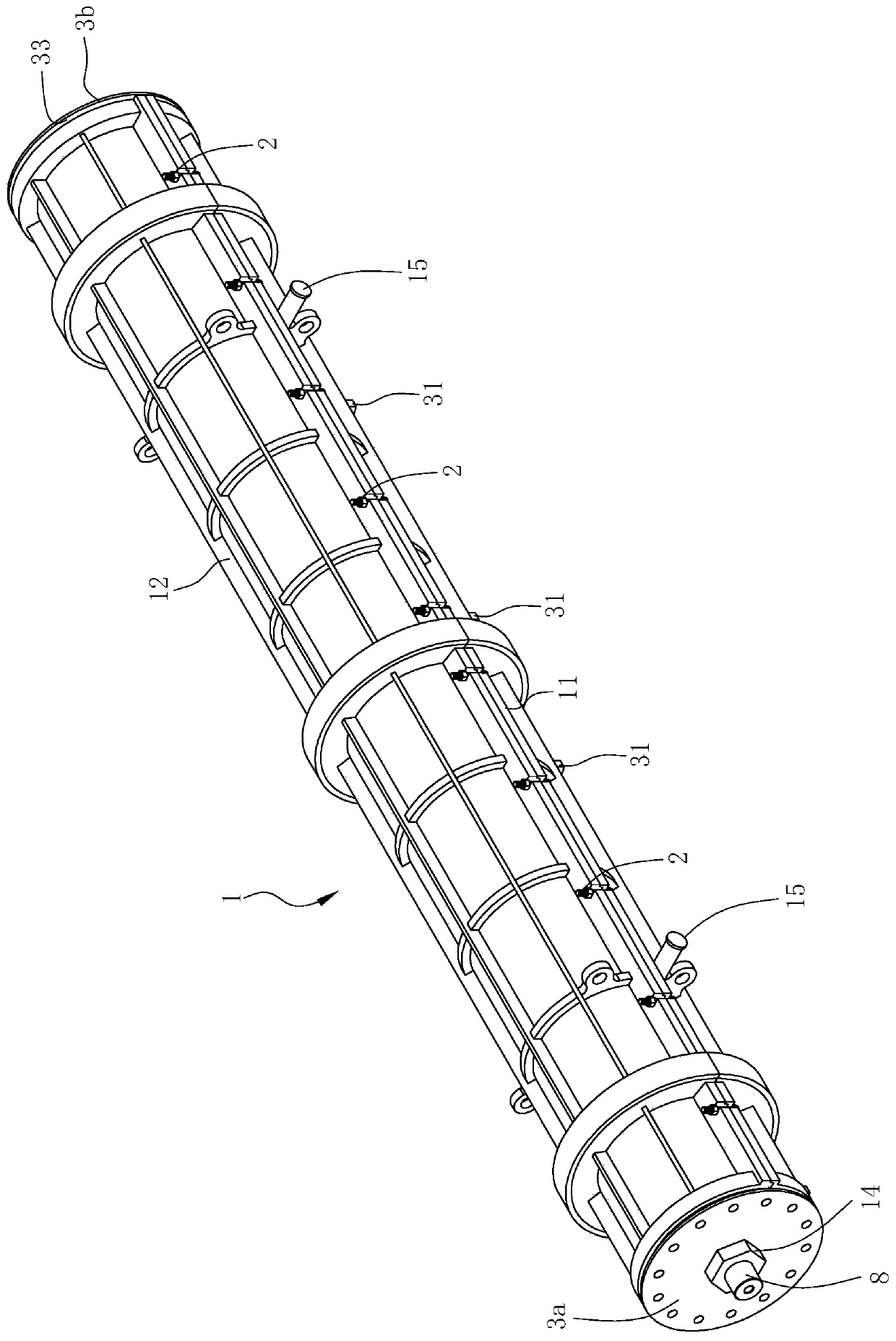
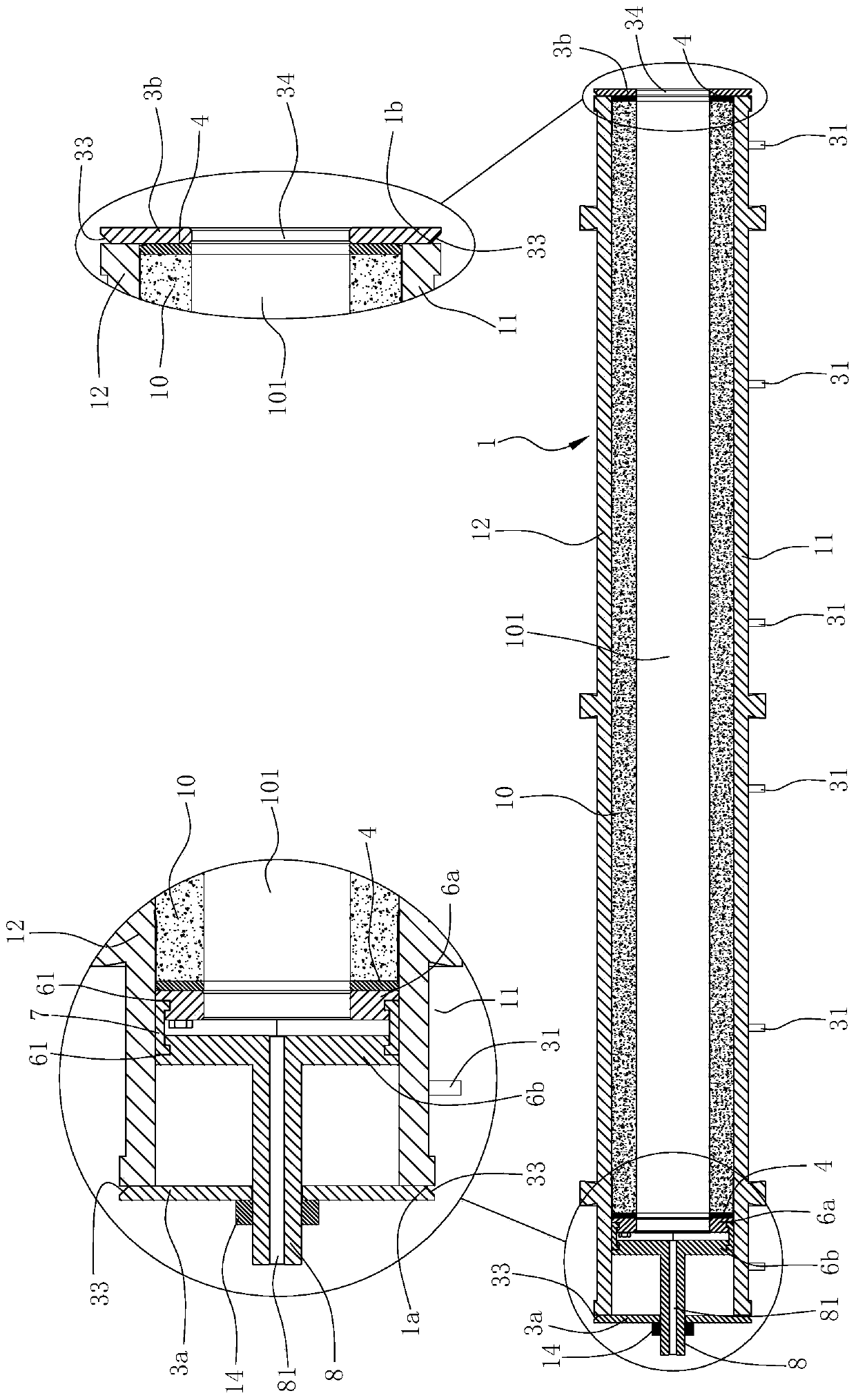
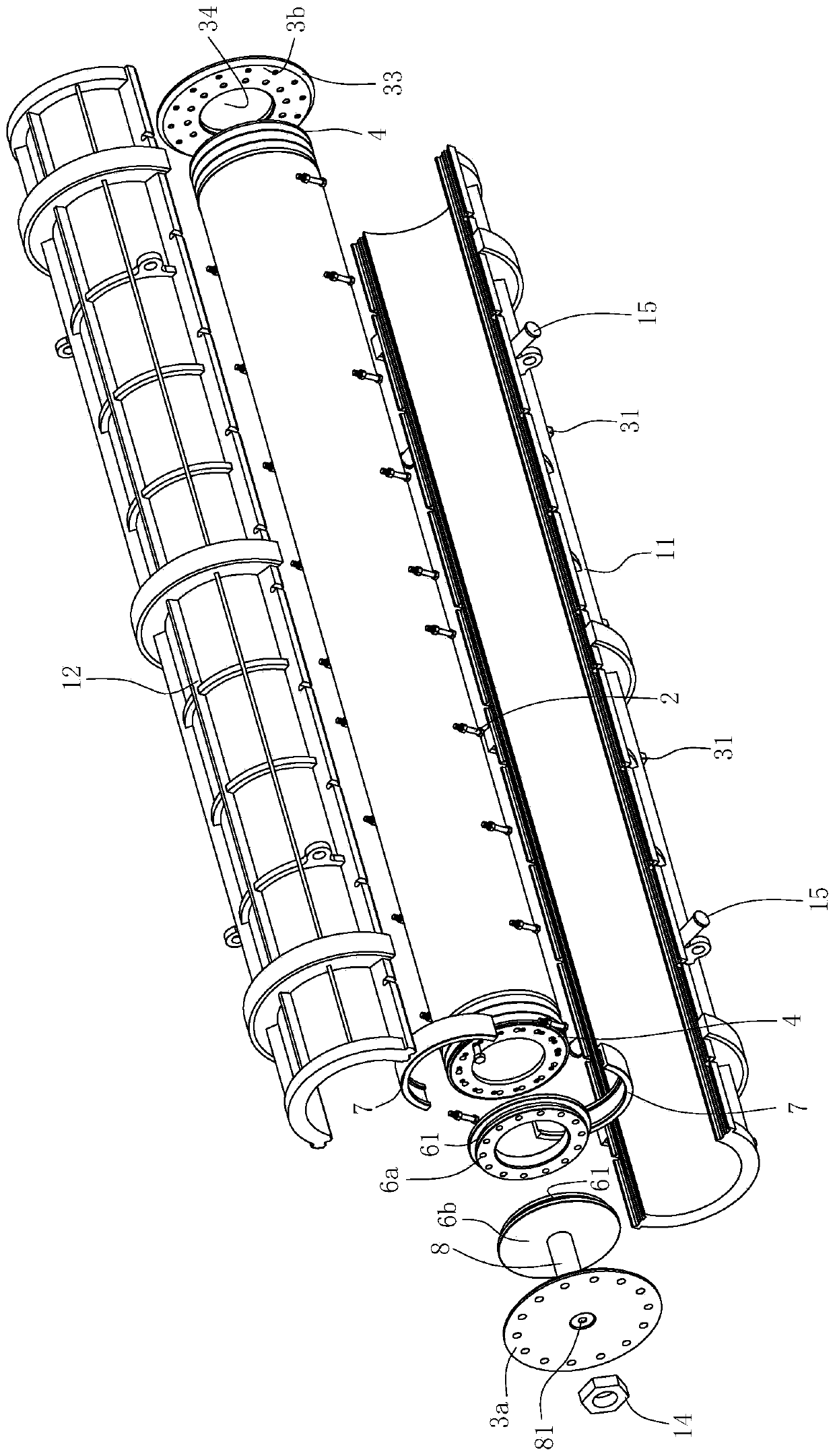
[0036] Such as Figure 1~4 Shown is the first embodiment of the centrifugal concrete pile mold of the present invention.

[0037] A centrifugal concrete pile mold, including a mold body 1 formed by the combination of a lower half mold 11 and an upper half mold 12, and a mold clamping bolt assembly 2 for connecting the lower half mold 11 and the upper half mold 12, and the mold body 1 A front support plate 3a and a rear support plate 3b are respectively fixed on the front end surface 1a and the rear end surface 1b; the peripheral edge of the end surface of the front support plate 3a and the rear support plate 3b which fits with the mold body 1 has an annular wedge-shaped surface 33 .

[0038] The mold is provided with a radially protruding positioning lug 31 that exposes the peripheral surface of the mold body 1 . The positioning lug 31 is pr...


PUM


Abstract

The invention relates to a centrifugal concrete pile mold which is composed of a mold body (1) folded by a lower half mold (11) and an upper half mold (12) and a mold closing bolt assembly (2) for connecting the lower half mold (11) and the upper half mold (12). A front supporting plate (3a) and a back supporting plate (3b) are separately fixed to a front end surface (1a) and a back end surface (1b) of the mold body (1). The mold body is characterized in that annular wedge-shaped surfaces (33) are arranged on the peripheries of the end surfaces, attached to the mold body (1), of the front supporting plate (3a) and the back supporting plate (3b). The mold is the centrifugal concrete pile capable of positioning mold closing of the mold precisely and provides probability that a mold hosting route and a centrifugal machine are on same axis, so that a centrifugal concrete pile production line is optimized favorably. The invention also relates to a flat car matched with the mold in use.

Description

technical field [0001] The invention relates to a mold for a centrifugal concrete pile and a flatbed truck for shelving the mold. Background technique [0002] Pretensioned prestressed centrifugal concrete pile is an important pile foundation material in my country, which belongs to the technical field of concrete products. Its factory production can be traced back to the 1960s. In the 1980s, with the As a kind of heavy-duty prefabricated component, its main process is to cut the steel bar to length, form the steel bar into a cage shape, install the end plate, put the steel bar cage with the end plate into the bottom mold, and clean the upper mold. And base formwork, coating release agent, concrete mixing, fabric distribution, mold clamping, tensioning, centrifugal forming, steam curing, formwork removal and other processes, in order to realize the factory production of centrifugal prefabricated piles, we need to adjust each The process is arranged to form a reasonable assembl...

Claims


Application Information

Patent Timeline
Patent Type & Authority Applications(China)
IPC IPC(8): B28B21/80B28B21/82B28B21/30B28B21/62
CPCB28B21/80B28B21/82B28B21/30B28B21/62
Inventor 俞晓东
Owner 俞晓东
Learn More