

Automatic wafer testing machine
An automatic testing machine and chip technology, applied in the direction of conveyor objects, transportation and packaging, etc., can solve the problems of increasing labor intensity, unfavorable production efficiency and production capacity, etc., to reduce labor intensity, improve efficiency and production capacity, and realize automated testing Effect
- Summary
- Abstract
- Description
- Claims
- Application Information
AI Technical Summary
Problems solved by technology
Method used
Image

Examples
Embodiment 1
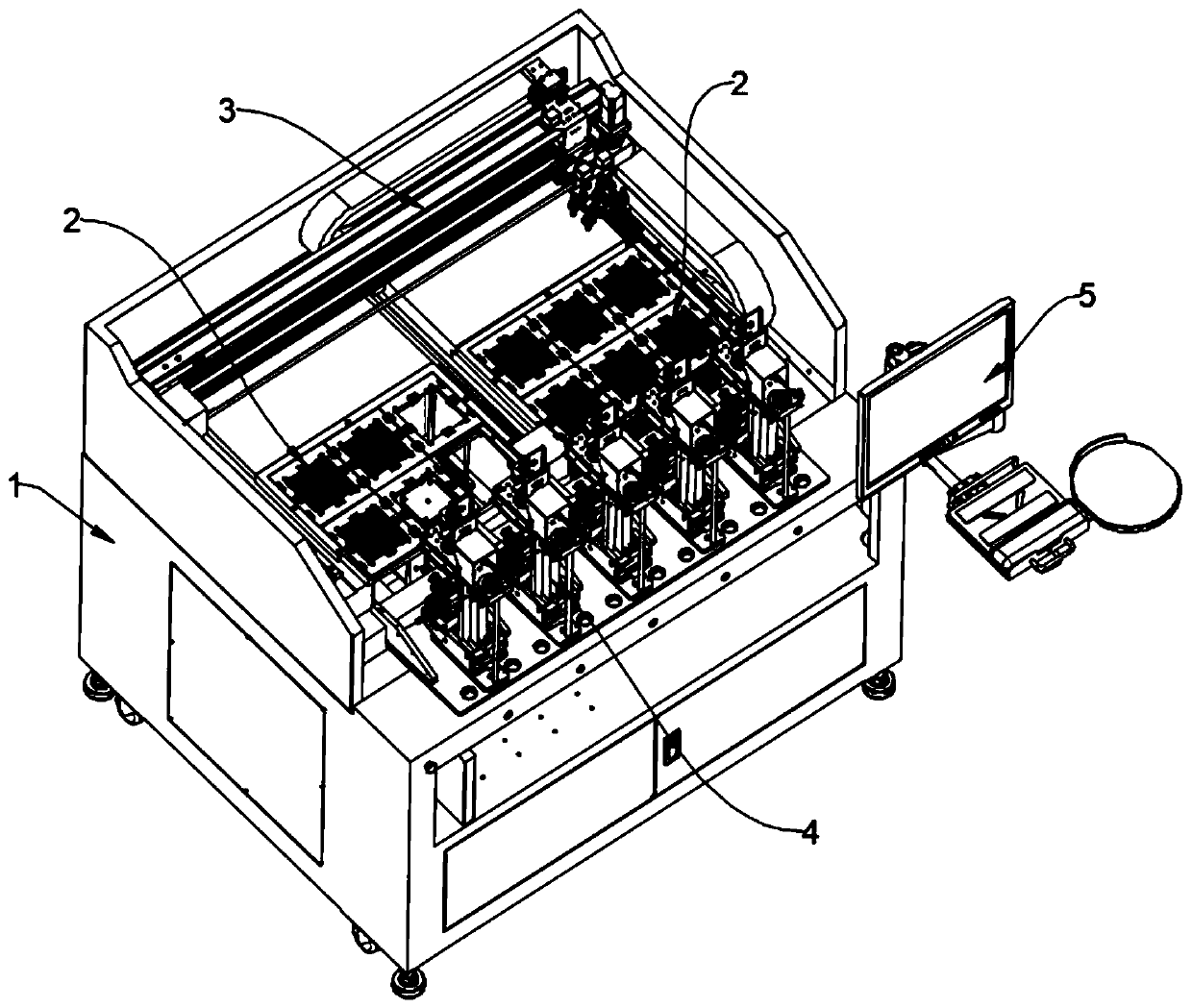
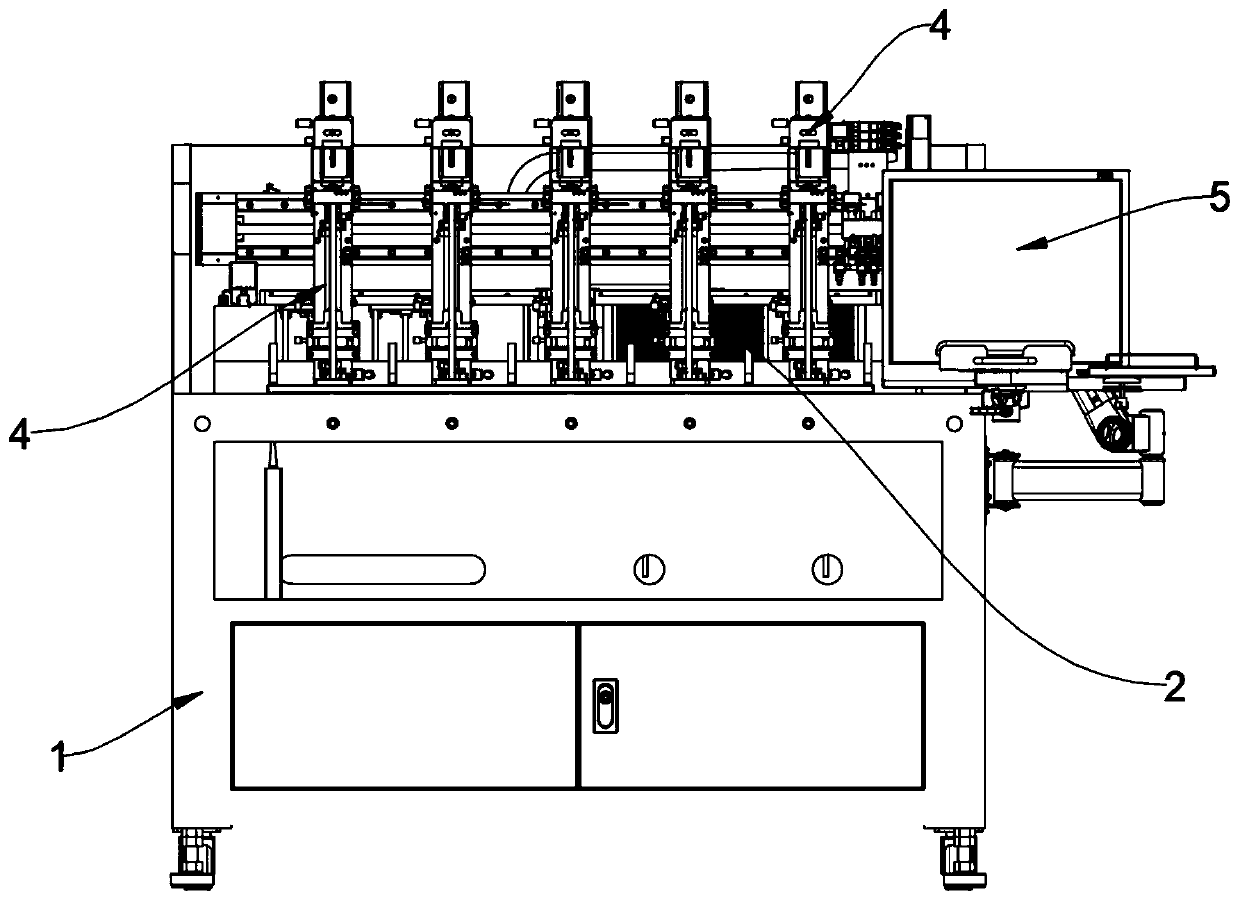
[0049] reference figure 1 with 2 As shown, this embodiment discloses an automatic wafer tester, which includes a frame 1, a transfer device 3 provided on the frame 1, a tray device 2, a test device 4, and a display device 5. The rack 1 is also provided with an electric control device, which mainly includes a PLC module, which is used to control the sequential actions of each device of the integrated wafer automatic tester, and realize the automatic operation of the wafer test. The display device 5 is configured to display the running status and test results of each device, which is convenient for manual real-time monitoring of the test process.
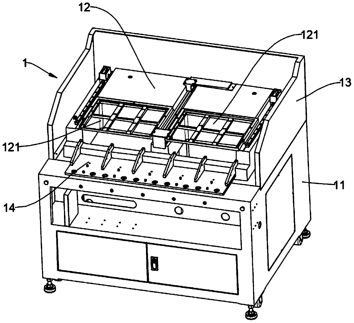
[0050] Specifically, refer to image 3 , The rack 1 includes a main body 11 and a bearing platform 12 arranged on the upper part of the main body 11, the main body 11 is used to accommodate the electric control device; the bearing platform 12 is used to carry the transfer device 3 and the tray device 2; optionally, The carrying platform ...
Embodiment 2
[0055] This embodiment is to provide a tray device 2 that can be used in the automatic wafer tester in the first embodiment. Specifically, refer to Figure 4 The tray device 2 includes a mounting top plate 21 and a mounting bottom plate 22. Optionally, the mounting top plate 21 and the mounting bottom plate 22 are spaced apart and connected by a connecting rod 23, which is vertically arranged between the mounting top plate 21 and the mounting bottom plate 22. Further, in order to enable the automatic testing machine to test more wafers, each tray device 2 is configured to allow a plurality of trays 100 to be stacked in the vertical direction between the mounting top plate 21 and the mounting bottom plate 22. In the space, the transfer device 3 completes the reciprocating movement of the wafer on the uppermost tray 100 between the tray device 2 and the test device 4 according to the instructions, or completes the empty tray in the test tray device and the empty tray device Trans...
Embodiment 3
[0064] This embodiment is to provide a transfer device 3 that can be used in the wafer automatic tester in the first embodiment. The transfer device 3 is configured to realize the tray 100 between different tray devices 2 and the wafer in the tray device The movement between 2 and the test device 4 completes the reclaiming or unwinding action. Specifically, refer to Figure 7 with Figure 8 , The transfer device 3 includes a first slide rail 311, a first drive assembly 33, a second slide rail 321, a second drive assembly 34, and a nozzle assembly 37. The nozzle assembly 37 includes a nozzle body 373 for directly sucking materials For the disk 100 or wafer, the first drive assembly 33 is configured to drive the nozzle assembly 37 to move along the first slide rail 311, and the second drive assembly 34 is configured to drive the nozzle assembly 37 and the first slide rail 311 integrally along the second slide The rail 321 moves, and the extension directions of the first slide rai...
PUM
 Abstract
Description
Claims
Application Information