
Automatic test system for millimeter wave receiver

A millimeter wave and receiver technology, applied in the field of automatic test systems, can solve the problems of affecting measurement accuracy, time-consuming and laborious, lack of measurement equipment, etc., and achieve the effect of improving measurement accuracy and speed

Inactive Publication Date: 2010-06-16
NAT SPACE SCI CENT CAS
View PDF1 Cites 27 Cited by
  • Summary
  • Abstract
  • Description
  • Claims
  • Application Information

AI Technical Summary

Problems solved by technology

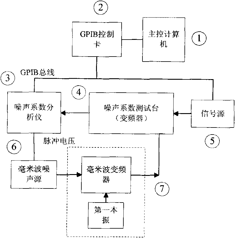
[0005] The purpose of the present invention is to overcome the need to manually input the frequency points to be measured through the control interface when measuring multiple millimeter wave receivers, which is time-consuming and laborious, resulting in fewer measurement frequency points and affecting measurement accuracy; at the same time, it overcomes some millimeter wave frequency band measurement equipment. lack of other problems, thus providing an automatic test system for millimeter wave receivers

Method used


Image

  • Automatic test system for millimeter wave receiver
  • Automatic test system for millimeter wave receiver
  • Automatic test system for millimeter wave receiver

Examples


Embodiment Construction

[0057] The automatic test system for the millimeter wave receiver of the present invention will be described in detail below with reference to the drawings and specific implementation.

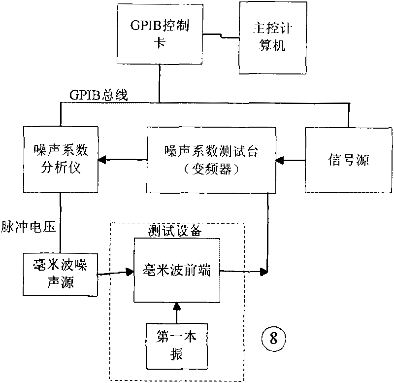
[0058] The framework of the noise figure test subsystem is as follows: figure 2 As shown, it consists of main control computer 1, GPIB control card 2, test equipment 8, noise figure analyzer 3, noise figure test frequency converter 4, signal source 5, millimeter wave noise source 6; the test is divided into noise figure analyzer calibration There are two parts: noise figure test and noise figure test; it is used to test and save the noise figure index of the front end of the millimeter wave receiver.

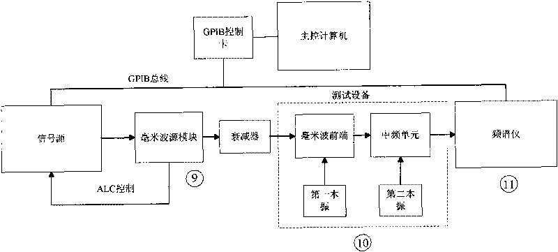
[0059] The framework of the amplitude-frequency characteristic test subsystem is as follows: image 3 As shown, it consists of a main control computer 1, a GBIP control card 2, a device under test 10, a signal source 5, a millimeter-wave spread spectrum source module 9, and a spectrum analyzer...


PUM


Abstract

The invention provides an automatic test system for a millimeter wave receiver. The system realizes automatic test for a noise coefficient, an amplitude-frequency characteristic, a multi-channel phase consistency index of the millimeter wave receiver in a mode of frequency scanning. The system comprises a noise coefficient test sub-system, an amplitude-frequency characteristic test sub-system anda phase consistency test sub-system. Each of the three sub-systems comprises a main control computer for automatic control, and a GPIB data card. The amplitude-frequency characteristic test sub-system and the phase consistency test sub-system also comprise a millimeter wave frequency multiplication module for performing frequency multiplication on signals to an operating frequency of a test device. The automatic test system can completely realize the automatic test for the radio frequency index of the millimeter wave receiver by utilizing the conventional test device, solves the problem that the conventional millimeter wave test method and test device in China are absent, and overcomes the defects that a manual test wastes much time and energy, data points are less and the accuracy is low.

Description

technical field [0001] The present invention relates to a test system for the millimeter wave band, in particular, the present invention relates to an automatic test system for a millimeter wave receiver. Background technique [0002] In recent years, millimeter-wave receivers have been more and more widely used in the fields of communication, remote sensing, and radar. Millimeter-wave receivers usually need to test their noise figure, amplitude-frequency characteristics, and phase consistency between channels. for analysis. [0003] At present, domestic millimeter-wave automatic test methods are relatively lacking. On the one hand, millimeter-wave test instruments are quite expensive, and the purchase cost is high for users, and some millimeter-wave frequency bands lack ready-made test instruments; on the other hand, the current millimeter-wave test is usually Manual test, for each test item, connect the corresponding instrument and the device under test, test through the ...

Claims


Application Information

Patent Timeline
IPC IPC(8): G01S7/40
Inventor 牛立杰刘浩张升伟吴季
Owner NAT SPACE SCI CENT CAS
Learn More