Cold radiation composite board

A composite board, cold radiation technology, applied in building components, heating methods, lighting and heating equipment, etc., can solve the problems of large spacing between panels, reduced heat transfer efficiency, heat loss, etc., to achieve dense channels and uniform heat transfer. High efficiency and large contact surface

Pending Publication Date: 2019-09-17
GUANGZHOU COMPTON ZHIGAO BUILDING MATERIALS
View PDF0 Cites 0 Cited by
  • Summary
  • Abstract
  • Description
  • Claims
  • Application Information

AI Technical Summary

Problems solved by technology

However, due to this contact, the medium changes multiple times, the heat transfer efficiency is reduced, some heat will be lost, and the energy consumption is increased.
At the same ti

Method used


Image

  • Cold radiation composite board
  • Cold radiation composite board
  • Cold radiation composite board

Examples


Embodiment 1

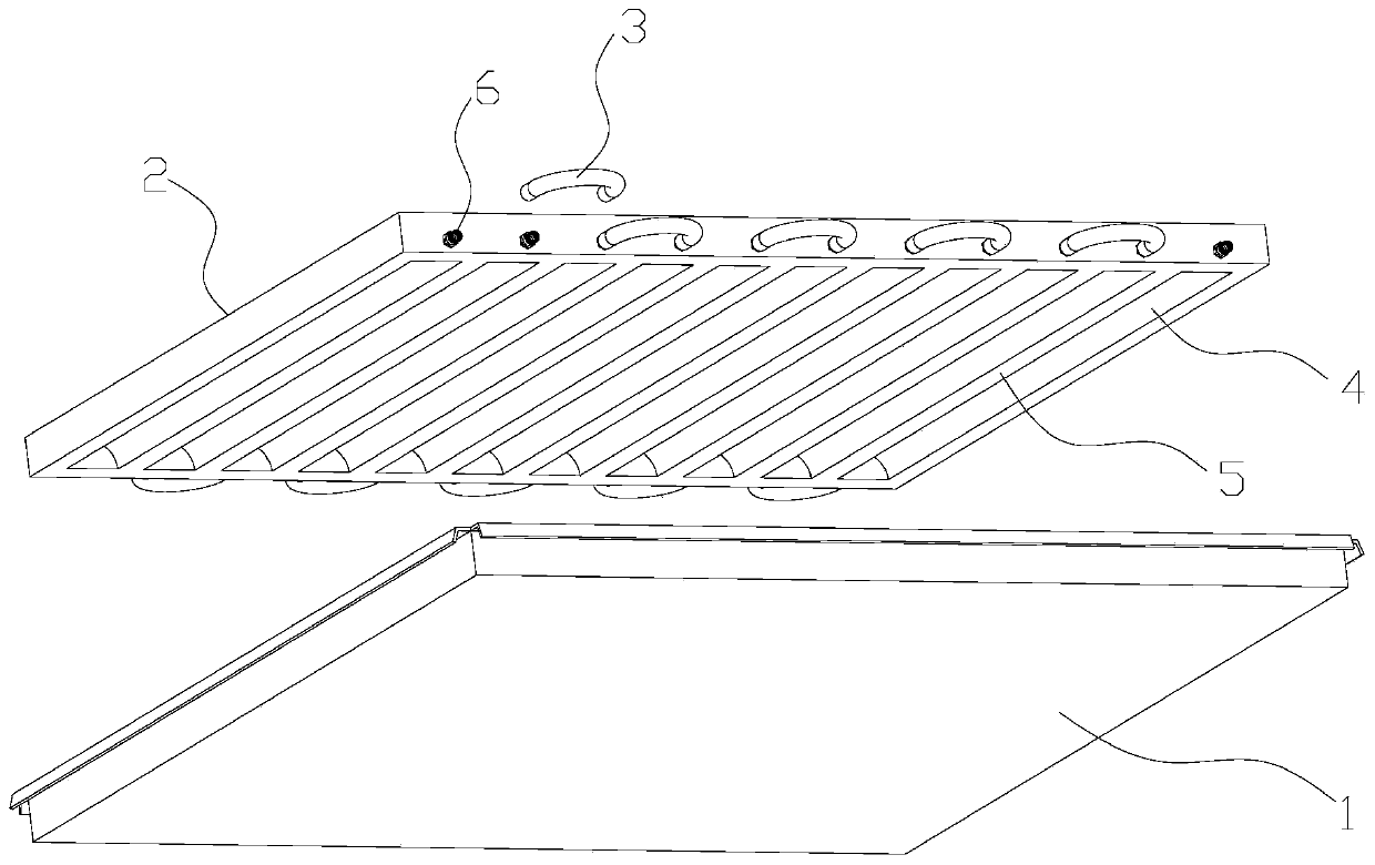
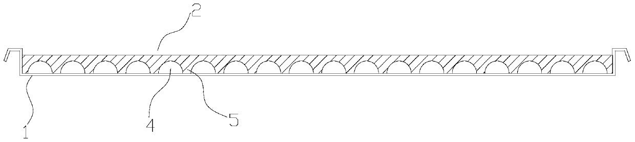
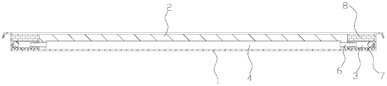
[0035] see Figure 1 to Figure 3 , the embodiment of the present invention provides a cold radiation composite panel, including a panel 1, a thermal insulation backplane 2 and a connecting pipeline 3; the edge of the panel 1 is bent and extended to the back to form a box shape; the thermal insulation backplane 2 is composed of Made of heat-insulating material, it is packaged on the back of the panel 1, and the inner surface of the heat-insulating back plate 2 is provided with a channel 4 for the circulation of the medium liquid. Spacer flange 5; connecting pipeline 3 is located on both sides of the heat insulation backboard 2 and connected to the end of each channel 4, so that all the channels 4 are connected to form a medium liquid channel.

[0036] The greatest feature of the present invention is that the back of the panel 1 does not have the traditional metal coil structure, but a directly sealed heat-insulating back plate 2 instead. The heat-insulating backboard 2 and the...

Embodiment 2

[0045] The only difference between the present embodiment and the first embodiment lies in the connection structure of the connecting pipeline 3, which makes the overall direction structure of the pipeline different.

[0046] see Figure 5 Specifically, preferably, the connecting pipeline 3 includes an inlet main pipe 9, an outlet main pipe 10 and a branch pipe 11; the inlet main pipe 9 extends along the arrangement direction of the channels 4 and is arranged at one end of the channel 4, through which the branch pipe 11 The inlet main pipe 9 communicates with each channel 4 ; the outlet main pipe 10 extends along the arrangement direction of the channels 4 and is arranged at the other end of the channel 4 , and the outlet main pipe 10 communicates with each channel 4 through a branch pipe 11 .

[0047] Different from the coiled pipeline structure of Embodiment 1, this embodiment adopts a straight-line pipeline structure, and the medium liquid is input through the inlet main pi...


PUM

PropertyMeasurementUnit
Thermal conductivityaaaaaaaaaa

Abstract

The invention provides a cold radiation composite board. The cold radiation composite board comprises a panel, a heat-insulation back plate and connecting pipelines; the edges of the panel are bent and extend towards the back face to form a box shape; the heat-insulation back plate is made of a heat-insulation material and is packaged on the back face of the panel, channels used for circulating medium liquid are formed in the inner surface of the heat-insulation back plate, and blocking and partitioning flanges are arranged between the channels in an inwards protruding mode; and the connecting pipelines are located on the two sides of the heat-insulation back plate and connected to the ends of all the channels, and all the channels communicate to constitute medium liquid channels. The heat-insulation back plate and the panels are combined in a sealed mode to directly constitute a pipeline allowing the medium liquid to flow, the cold radiation efficiency is improved, and cold radiation is more uniform.

Description

technical field [0001] The invention relates to the technical field of building materials and indoor cooling, in particular to a cold radiation composite board. Background technique [0002] Cold radiation technology was proposed by foreign countries and introduced into China many years ago. After years of technological development, its technological breakthroughs are mainly in the field of control systems, and the improvement of materials and structures has stagnated for many years. [0003] In the traditional cold radiant panel, a water-cooled coil is laid on the back of the metal plate, and the coil and the metal plate are independent of each other, which is for the convenience of production and assembly. Copper tubes are used for coils, and metal plates are in close contact with them for heat transfer. However, due to this kind of contact, the medium changes many times, the heat transfer efficiency is reduced, some heat will be lost, and the energy consumption is increa...

Claims


Application Information

Patent Timeline
IPC IPC(8): E04B9/00E04B9/04E04B2/74F24F5/00
CPCE04B2/74E04B9/00E04B9/04E04B9/0421E04B9/045F24F5/0089
Inventor 陈木华刘金龙吴海北
Owner GUANGZHOU COMPTON ZHIGAO BUILDING MATERIALS
Why Eureka
Try Eureka