Clamp ammeter based on Rogowski coil

A technology of clamp ammeter and Rogowski coil, which is applied in the direction of measuring current/voltage, measuring electrical variables, measuring devices, etc. It can solve the problems of difficulty in emergency repairs, measurement of wires that cannot be dispersed, and small bayonets, etc., so as to reduce the power outage time of faults , Reduce personal electric shock injury accidents, and facilitate connection

Pending Publication Date: 2019-09-17
STATE GRID ZHEJIANG HANGZHOU CITY FUYANG DISTRICT POWER SUPPLY CO LTD +1
View PDF0 Cites 5 Cited by
  • Summary
  • Abstract
  • Description
  • Claims
  • Application Information

AI Technical Summary

Problems solved by technology

[0002] When the existing power equipment fails, especially when the general protection trips and the power is cut off, to determine the leakage fault point, generally use a clamp-type ammeter to conduct an overall inspection of all the lines in the entire station area. Current, but the existing clamp-type ammeter bayonet is small, and it is often impossible to measure scattered wires or thick cables, which brings great difficulty to emergency repairs

Method used


Image

  • Clamp ammeter based on Rogowski coil
  • Clamp ammeter based on Rogowski coil
  • Clamp ammeter based on Rogowski coil

Examples


Embodiment 1

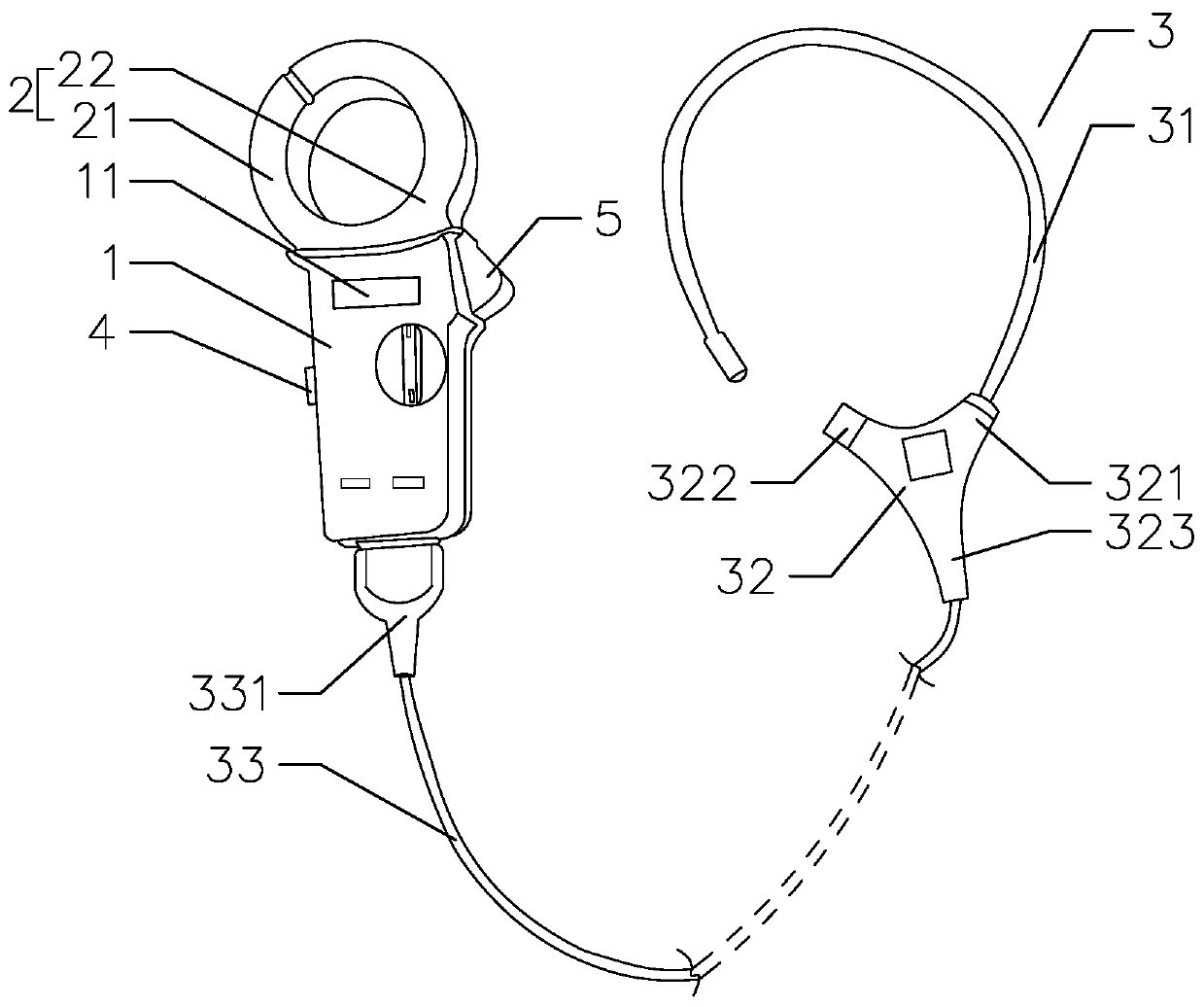
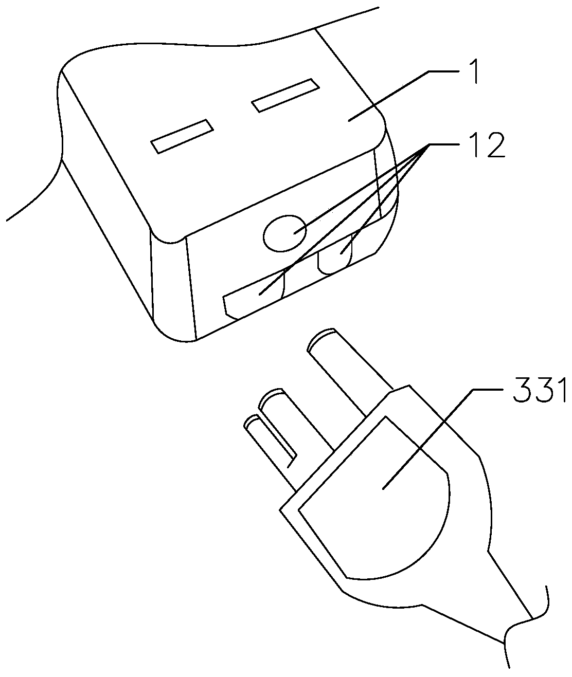
[0034] Such as Figures 1 to 2 As shown, the present invention provides a kind of pincer ammeter based on Rogowski coils, comprising a housing 1, a detection jaw 2 arranged at the upper end of the housing 1, a circuit board (not shown) arranged in the housing 1 and The battery (not shown) that supplies power to the circuit board and the detection jaw 2, the housing 1 is a plastic housing, the detection jaw 2 is electrically connected to the circuit board, and the housing 1 is provided with a display screen 11, the display screen 11 It is electrically connected with the circuit board, and the display screen 11 is fixed on the circuit board by soldering to form an electrical connection. The battery is a rechargeable battery. After the power of the battery is exhausted, the battery can be charged to realize recycling, energy saving and environmental protection.

[0035] In this embodiment, the clamp ammeter also includes a Rogowski coil 3 electrically connected to the circuit boa...

Embodiment 2

[0041] The difference between this embodiment and the first embodiment is that the outer peripheral cover of the detection jaw is provided with a shielding cover for shielding other conductive parts.

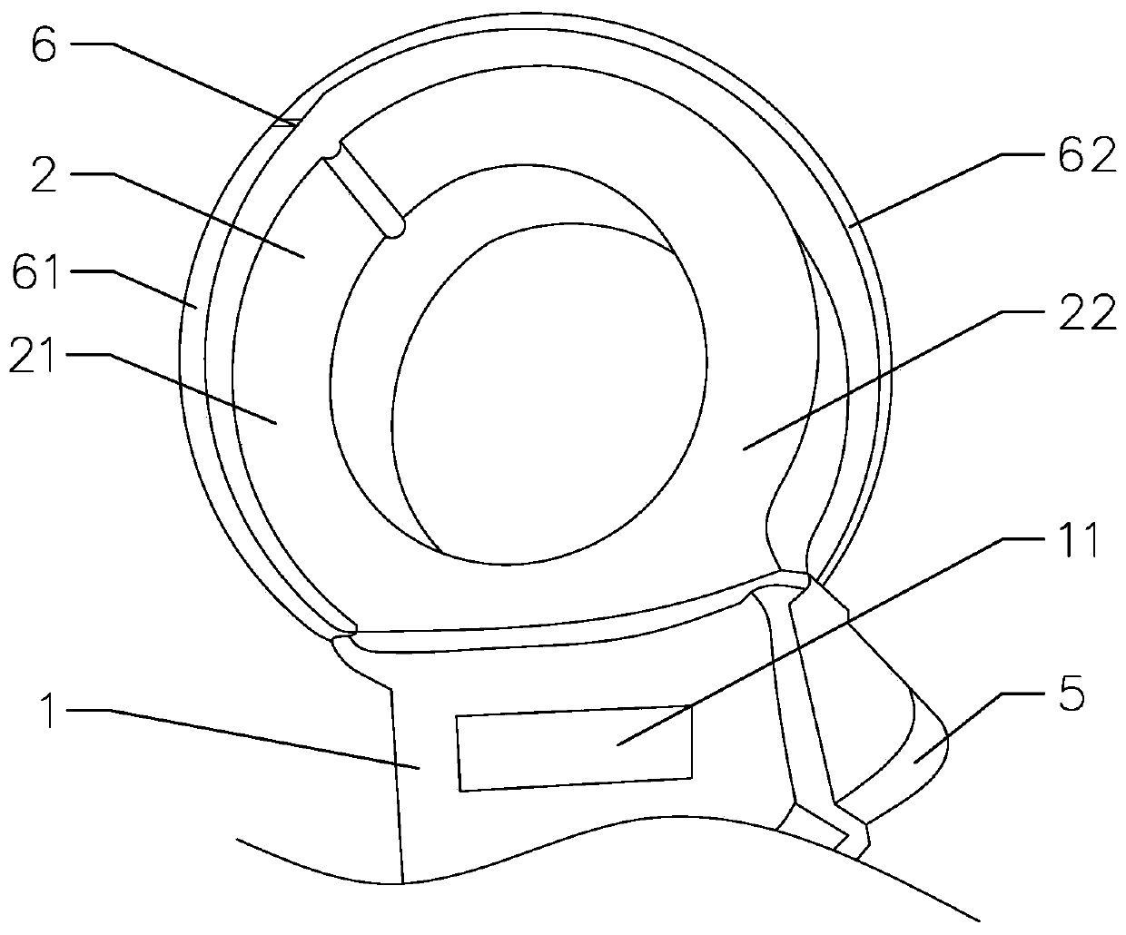
[0042] In this example, if image 3 As shown, the outer peripheral cover of the detection jaw 2 is provided with a shielding cover 6 for shielding other conductive parts, so that the detection jaw will not be affected by other conductive parts or power equipment when detecting electric equipment, thereby improving the detection jaw. The accuracy of detection and measurement can accurately locate fault customers, help customers troubleshoot in time, reduce fault outage time, and improve line power supply reliability.

[0043] Specifically, the detection jaw 2 is circular after closing, and the shape of the shielding cover 6 is matched with the shape of the detection jaw 2, that is, the shielding cover 6 is also circular, which can well ensure the maximum detection of the detectio...

Embodiment 3

[0047] The difference between this embodiment and the second embodiment lies in that the structure of the shielding case is different.

[0048] In this example, if Figure 4 As shown, the shielding cover 6 is an integral structure, and the movable cover of the shielding cover 6 is arranged on the outer periphery of the detection jaw and is detachably connected with the housing, so that after the detection and measurement are completed, the shielding cover can be removed and stored for convenience. The overall storage of the rectangular ammeter.

[0049] The structures and beneficial effects of other parts not described are the same as those in Embodiment 2, and will not be repeated here.


PUM


Abstract

The invention provides a clamp ammeter based on a Rogowski coil. The ammeter comprises a shell, a detection jaw, a circuit board and a battery, wherein the detection jaw is electrically connected with the circuit board, a display screen is arranged on the shell, and the display screen is electrically connected with the circuit board. The ammeter further comprises a Rogowski coil electrically connected with the circuit board, a selector switch is arranged on the side wall of the shell and electrically connected with the circuit board, and the selector switch is provided with a first gear and a second gear. When the selector switch is switched to the first gear, the detection jaw works, and when the selector switch is switched to the second gear, the Rogowski coil works, so that the detection jaw and the Rogowski coil of the clamp ammeter can work independently, namely the clamp ammeter has two detection functions, and the multifunction of the clamp ammeter is greatly improved; and when the condition that is not suitable for detecting the detection jaw is met, the Rogowski coil can be used for detecting and measuring, so that the detection convenience of the clamp ammeter and the maintenance convenience of maintenance personnel can be well improved.

Description

technical field [0001] The invention relates to a detection tool for electrical equipment, in particular to a clamp ammeter based on a Rogowski coil. Background technique [0002] When the existing power equipment fails, especially when the general protection trips and the power is cut off, to determine the leakage fault point, generally use a clamp-type ammeter to conduct an overall inspection of all the lines in the entire station area. current, but the existing clamp-type ammeter bayonet is small, and it is often impossible to measure scattered wires or thick cables, which brings great difficulty to emergency repairs. Contents of the invention [0003] The object of the present invention is to provide a clamp ammeter with convenient detection and maintenance. [0004] In order to achieve the above object, the present invention adopts the following technical solutions: a pincer ammeter based on Rogowski coils, including a housing, a detection jaw located on the upper en...

Claims


Application Information

Patent Timeline
Patent Type & Authority Applications(China)
IPC IPC(8): G01R19/00G01R1/04
CPCG01R1/04G01R19/00
Inventor 马国泉项翔王晓冲马腾楼英刘军凯花秀峰俞建飞夏军强来庆松高雪元周波葛国生姜松年徐贤祥徐成君华云波汤国民
Owner STATE GRID ZHEJIANG HANGZHOU CITY FUYANG DISTRICT POWER SUPPLY CO LTD
Why Eureka
Try Eureka