
filter

A filter and resonator technology, applied in waveguide-type devices, circuits, electrical components, etc., can solve problems such as poor filter applicability, and achieve the effect of improving applicability

Active Publication Date: 2021-05-18
SHENZHEN UNIV
View PDF8 Cites 0 Cited by
  • Summary
  • Abstract
  • Description
  • Claims
  • Application Information

AI Technical Summary

Problems solved by technology

[0003] The main purpose of the present invention is to provide a filter, which aims to solve the technical problem of poor filter applicability in the prior art

Method used


Image

  • filter
  • filter
  • filter

Examples


Embodiment Construction

[0022] In order to make the purpose, features and advantages of the present invention more obvious and understandable, the technical solutions in the embodiments of the present invention will be clearly and completely described below in conjunction with the accompanying drawings in the embodiments of the present invention. Obviously, the described The embodiments are only some of the embodiments of the present invention, but not all of them. Based on the embodiments of the present invention, all other embodiments obtained by those skilled in the art without making creative efforts belong to the protection scope of the present invention.

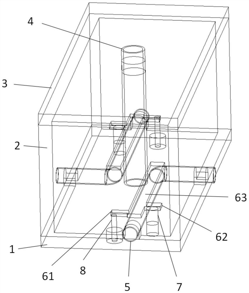
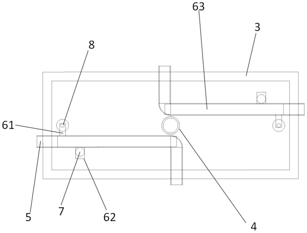
[0023] figure 1 is a schematic perspective view of a filter according to an embodiment of the present invention. figure 2 is a cross-sectional view of a filter according to an embodiment of the present invention.

[0024] As can be seen from the figure, the filter can have a housing, a first tubular object 5, a resonator 63 and a second tu...


PUM


Abstract

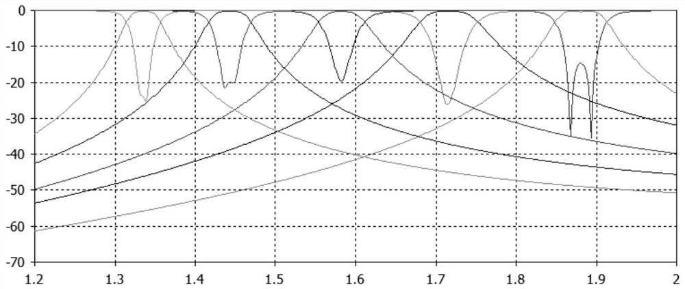
The invention relates to a filter. The filter includes a casing, a first tubular object, a resonator and a second tubular object. The casing includes a bottom plate, a side plate and a cover plate, and a through hole is opened on the cover plate. By changing the liquid volume in the first tube, the dielectric constant in the first tube is changed, so that the equivalent wavelength in the filter is changed, thereby adjusting the resonant frequency in the filter; by changing the second The volume of liquid in the tube changes the dielectric constant in the second tube and therefore changes the coupling strength in the filter, thereby separating the resonant frequencies in the filter such that the filter changes at the resonant frequency In this case, the fractional bandwidth remains constant. By adjusting the resonant frequency in the filter, the filter can be applied in different scenarios, thus improving the applicability of the filter.

Description

technical field [0001] The invention relates to the field of electronic components, in particular to a filter. Background technique [0002] A microwave filter is a device used to separate different microwave frequencies. It can suppress unwanted frequency signals and only allow the required frequency signals to pass through. It plays a very important role in the transmitting and receiving ends of the communication system. However, once the traditional microwave filter is processed, the passband of the microwave filter (the frequency range that the filter can pass through) is fixed, resulting in poor applicability of the existing microwave filter. Contents of the invention [0003] The main purpose of the present invention is to provide a filter to solve the technical problem of poor filter applicability in the prior art. [0004] In order to solve the problems of the technologies described above, the technical solution provided by the invention is: [0005] A filter, co...

Claims


Application Information

Patent Timeline
Patent Type & Authority Patents(China)
IPC IPC(8): H01P1/20
CPCH01P1/20
Inventor 王世伟谢杰恩袁芊芊周克宇陈瑞森郭建珲陈国文胡雄敏
Owner SHENZHEN UNIV
Learn More