Hydrogen concentration sensor based on microstrip antenna and system thereof

A concentration sensor and microstrip antenna technology, applied in antennas, instruments, scientific instruments, etc., can solve the problems of low sensitivity, poor safety performance, explosion, etc., and achieve the effect of high sensitivity, accuracy and precision

Inactive Publication Date: 2020-11-06
中山科立特光电科技有限公司
View PDF0 Cites 3 Cited by
  • Summary
  • Abstract
  • Description
  • Claims
  • Application Information

AI Technical Summary

Problems solved by technology

[0004] The object of the present invention is to, aim at above-mentioned deficiencies in the prior art, provide a kind of hydrogen concentration sensor and its system based on the microstrip antenna, to solve what adopt in the prior art is the electrochemical hydrogen concentration sensor, the electrochemical hydrogen concentration sensor It is easy to generate electric sparks during use, causing explosions, poor safety performance, and low sensitivity

Method used


Image

  • Hydrogen concentration sensor based on microstrip antenna and system thereof
  • Hydrogen concentration sensor based on microstrip antenna and system thereof
  • Hydrogen concentration sensor based on microstrip antenna and system thereof

Examples


Embodiment 1

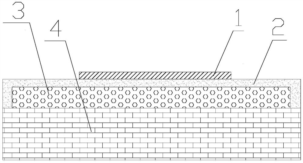
[0027] figure 1 A schematic cross-sectional view of a hydrogen concentration sensor based on a microstrip antenna provided in an embodiment of the present invention; as figure 1 Shown, the present invention provides a kind of hydrogen concentration sensor based on microstrip antenna, and hydrogen concentration sensor comprises: radiation patch 1, sensitive adsorption layer 2, insulating layer 3 and grounding plate 4; On one side, the sensitive adsorption layer 2 is wrapped on the side and surroundings of the insulating layer 3 away from the grounding plate 4, the radiation patch 1 is arranged on the side of the sensitive adsorption layer 2 away from the grounding plate 4, and the radiation patch 1 and the grounding plate 4 The material is a metal good conductor material, and the material of the sensitive adsorption layer 2 is a hydrogen sensitive material.

[0028] The insulating layer 3 is arranged above the grounding plate 4, and the sensitive adsorption layer 2 is arranged...

Embodiment 2

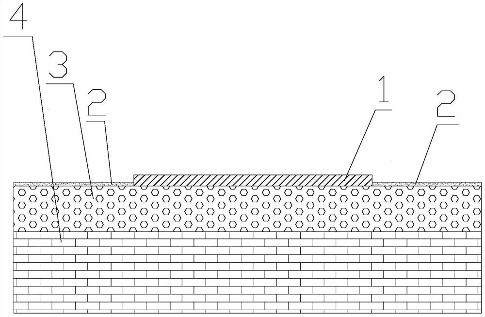
[0045] figure 2 A schematic cross-sectional view of another hydrogen concentration sensor based on a microstrip antenna provided in an embodiment of the present invention; as figure 2 As shown, the hydrogen concentration sensor of another microstrip antenna in this embodiment is basically the same as that of Embodiment 1, the only difference is that the insulating layer 3 is set close to the ground plate 4, and the radiation patch 1 is set on the insulating layer 3 away from the ground plate 4. In the middle of one side, the sensitive adsorption layer 2 is arranged at both ends of the insulation layer 3 away from the ground plate 4 , that is, the two parts of the sensitive adsorption layer 2 are arranged on both sides of the radiation patch 1 respectively.

[0046] Since the sensitive adsorption layer 2 is directly located on the upper surface of the insulating layer 3 , it is more convenient to prepare the sensitive adsorption layer 2 and the insulating layer 3 experimental...

Embodiment 3

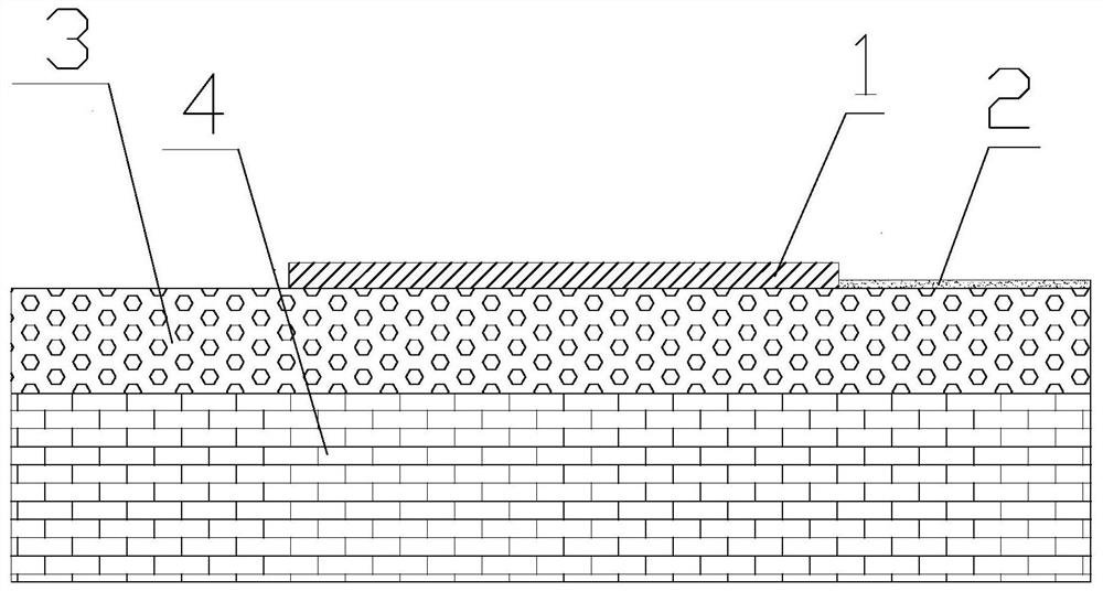
[0049] image 3 A schematic cross-sectional view of another hydrogen concentration sensor based on a microstrip antenna provided in an embodiment of the present invention; as image 3 As shown, the hydrogen concentration sensor of another microstrip antenna in this embodiment is basically the same as that of Embodiment 1, the only difference is that the insulating layer 3 is set close to the ground plate 4, and the radiation patch 1 is set on the insulating layer 3 away from the ground plate 4. In the middle of one side, the sensitive adsorption layer 2 is arranged on the end of the insulation layer 3 away from the ground plate 4 , that is, the sensitive adsorption layer 2 is arranged on one side of the radiation patch 1 respectively.

[0050] In this way, when the hydrogen concentration changes, the dielectric substrate composed of the sensitive adsorption layer 2 and the insulating layer 3 will change unevenly, thereby more easily causing the change of the resonant frequency...


PUM


Abstract

The invention relates to a hydrogen concentration sensor based on a microstrip antenna and a system thereof, in particular to the field of hydrogen sensing. The sensitive adsorption layer of the hydrogen concentration sensor is made of a hydrogen sensitive material. The hydrogen sensitive material is relatively sensitive to hydrogen, and absorbing surrounding hydrogen, the dielectric constant andthe volume are changed. When the hydrogen concentration around the hydrogen concentration sensor is relatively high, the hydrogen sensitive adsorption layer absorbs hydrogen in the surrounding air, the distance and the dielectric constant between the radiation patch and the grounding plate are changed. The microstrip antenna is composed of the radiation patch, the sensitive adsorption layer, the insulating layer and the grounding plate. The resonant frequency of the microstrip antenna is related to the distance between the radiation patch and the grounding plate and the dielectric constant. Bymeasuring the change condition of the resonant frequency of the microstrip antenna and according to the corresponding relation between the change condition of the resonant frequency of the microstripantenna and the hydrogen concentration, the hydrogen concentration to be measured is obtained.

Description

technical field [0001] The invention relates to the field of hydrogen sensing, in particular to a microstrip antenna-based hydrogen concentration sensor and a system thereof. Background technique [0002] As a clean new energy, hydrogen has been widely used in many fields such as petrochemical, electronics, metallurgy, aerospace and automobile. However, hydrogen has extremely low density, high diffusion coefficient, colorless, odorless, flammable and explosive, and its existence cannot be detected by human senses, so the safe storage and transportation of hydrogen is not easy. Therefore, it is very important to detect hydrogen leakage and quantify the gas concentration during production, storage and transportation. Therefore, the preparation of gas sensors that are extremely sensitive and accurate to hydrogen is very important for the wide application of hydrogen energy and the safety of social production and life. [0003] In the prior art, an electrochemical hydrogen conc...

Claims


Application Information

Patent Timeline
Patent Type & Authority Applications(China)
IPC IPC(8): G01N27/416H01Q1/38H01Q13/08
CPCG01N27/4162H01Q1/38H01Q13/08
Inventor 不公告发明人
Owner 中山科立特光电科技有限公司
Why Eureka
Try Eureka