Radome and method of producing the same

a technology of radome and radome, which is applied in the direction of envelope/bag making machinery, paper/cardboard containers, pedestrian/occupant safety arrangements, etc., can solve the problems of increased radio wave transmission loss, easy plastic deformation of radome using such a material, slippery interface between organic fiber and matrix, etc., and achieves excellent radio wave transmission loss and structural strength, easy production, and favorable workability

Active Publication Date: 2011-10-25
MITSUBISHI ELECTRIC CORP
View PDF12 Cites 3 Cited by
  • Summary
  • Abstract
  • Description
  • Claims
  • Application Information

AI Technical Summary

Benefits of technology

The inventors of the present invention have conducted extensive research in order to solve the above-mentioned problems. As a result, the inventors of the present invention found that: by impregnating an olefin woven material and a glass cloth with a matrix resin to thereby integrate them, changes in the dielectric constant in a radome material can be reduced while reflecting the low dielectric constant of the olefin woven material; and by disposing a glass cloth at the inner side of a radome where the radome is most severely distorted by a load applied to the radome in the bending direction from the outside environment side, the glass cloth and the matrix resin easily form a hydrogen bond to thereby increase the structural strength, to thus accomplish the present invention.
The present invention can provide a radome which has excellent transmission loss of radio waves and structural strength, which can be easily produced, and which has favorable workability, and a method of producing the same.

Problems solved by technology

Thus, a radome using such a material has increased transmission loss of radio waves.
However, since organic fibers having a low dielectric constant generally have a weak adhesion force with a matrix resin, the interface between the organic fiber and the matrix becomes slippery.
As a result, a radome using such a material is likely to suffer from plastic deformation when distortion in the bending direction is applied by a load such as wind.
However, since the dielectric constant of the core is considerably different from the dielectric constant of the composite material facing, reflection is likely to occur when a radio wave transmits between the composite material facing and the core and, moreover, the number of side lobes increases remarkably, resulting in increased transmission loss of radio waves.
Further, a method of producing a radome using sandwich structure panels has problems with workability.
More specifically, although it is possible to form a radome having a curved surface shape, it is difficult to form a radome having an angled portion.
Specifically, when the core material of the sandwich structure panels is folded or two or more of the core materials are connected in producing the sandwich structure panels, the density becomes coarse due to the formation of cracks and compression parts in the core material, which become a singular point of the dielectric constant, resulting in increased transmission loss of radio waves.
Moreover, in the method of producing a radome using sandwich structure panels, the first composite material facing, the second composite material facing, and the core are produced separately, and then the composite material facings and the core need to be laminated with each other, giving rise to problem that the production process is complicated.

Method used


Image

  • Radome and method of producing the same
  • Radome and method of producing the same
  • Radome and method of producing the same

Examples


embodiment 1

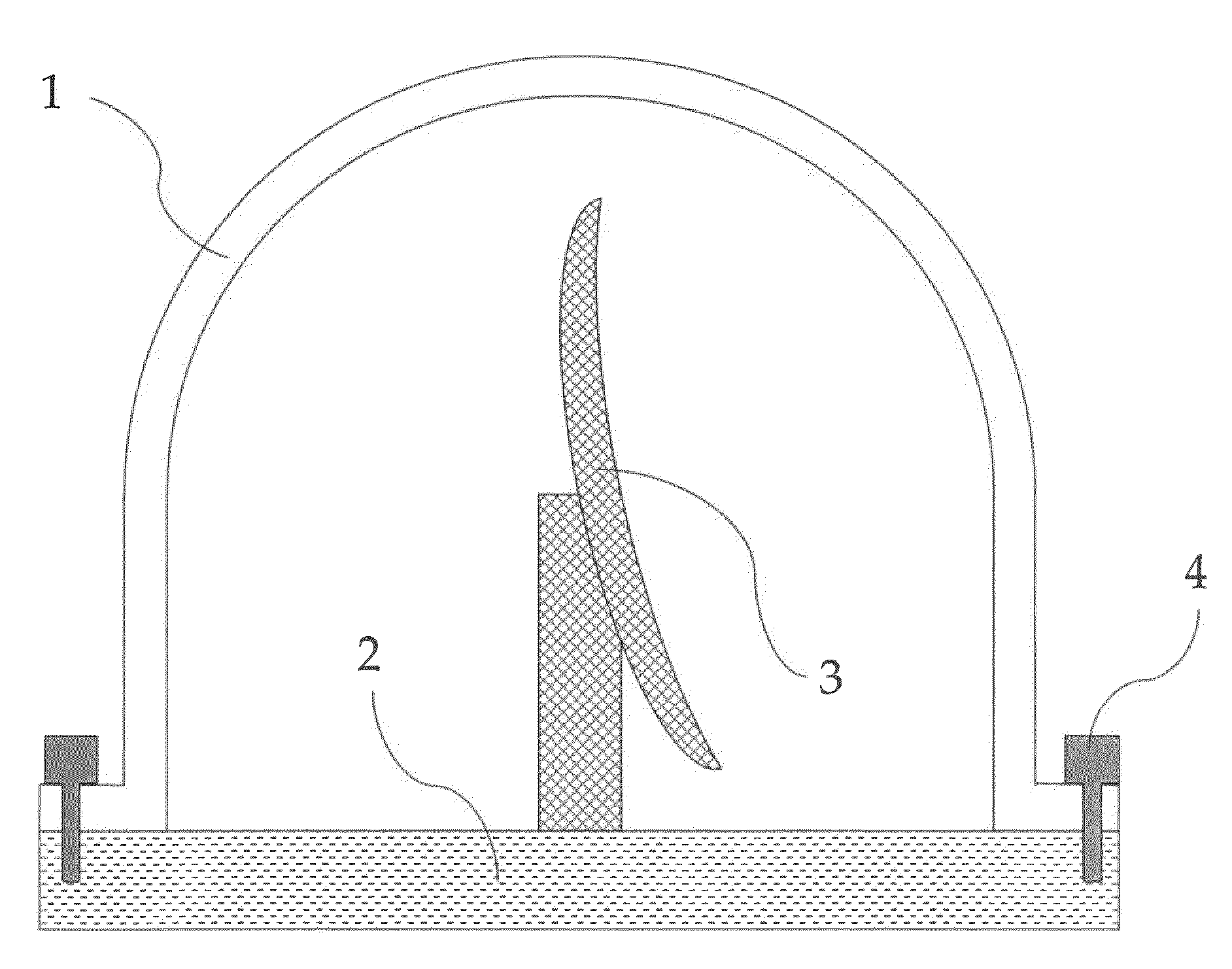
FIG. 1 is a view for explaining a radome according to this embodiment. In FIG. 1, a radome 1 is fixed to a base 2 with fixing screws 4, and a radio wave device 3 containing an antenna is disposed inside the radome 1.

The radome 1 protects the radio wave device 3 from the outside environment (e.g., natural environment such as wind, sunlight, rain, and seawater, impact from the outside, and dust). When a radio wave is received / transmitted between the outside and the antenna, the radio wave passes through the radome 1. Here, although the shape of the radome 1 may be suitably determined, if the radio wave device 3 moves, the radome 1 must be structured in such a manner that it does not interfere with the radio wave device 3. Moreover, the radome I is disposed in such a manner that the distance from the central part of the antenna to the radome 1 is as equal as possible in the direction of the output radio wave of the antenna and that a radio wave enters perpendicular to the radome 1.

In o...

embodiment 2

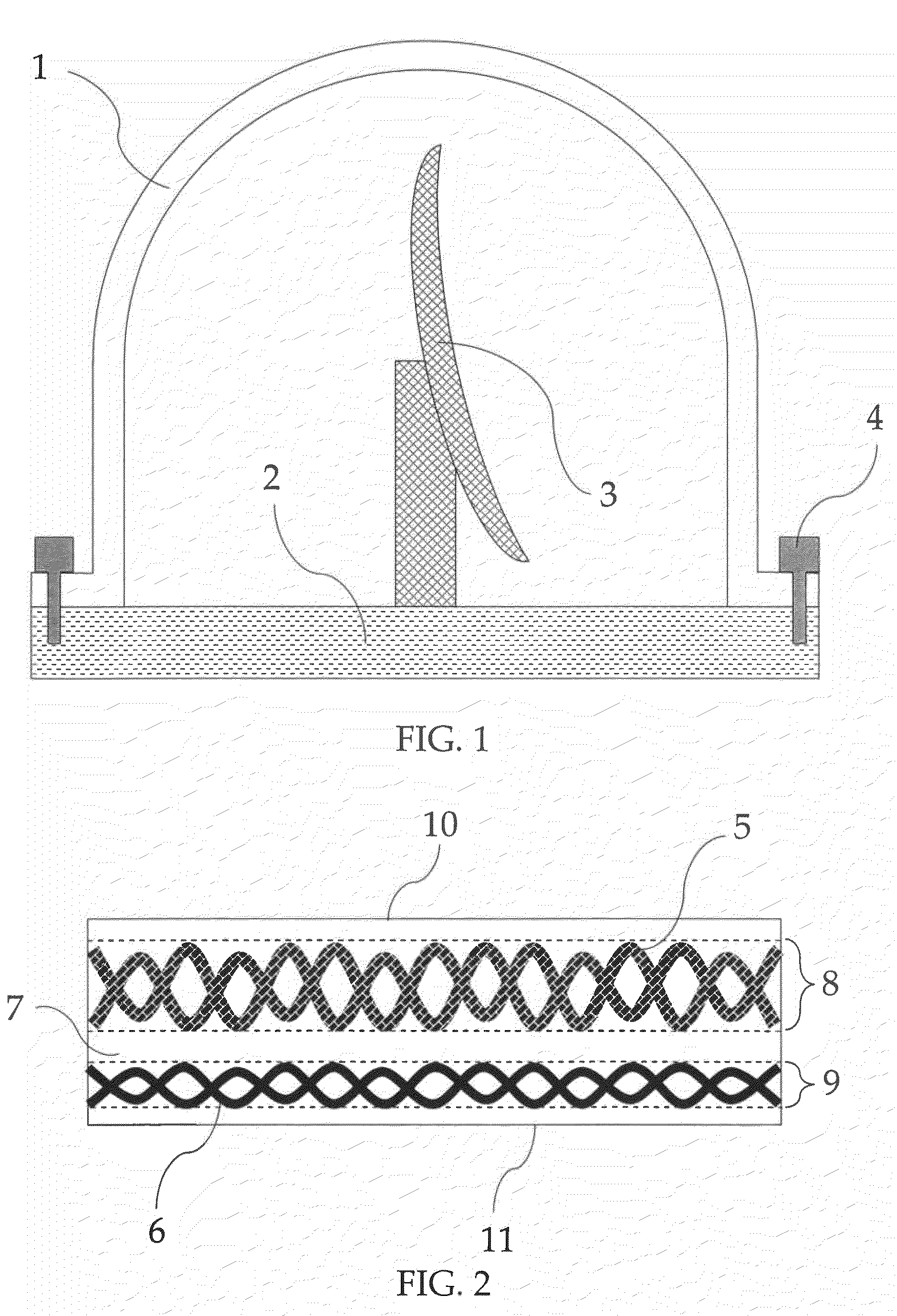
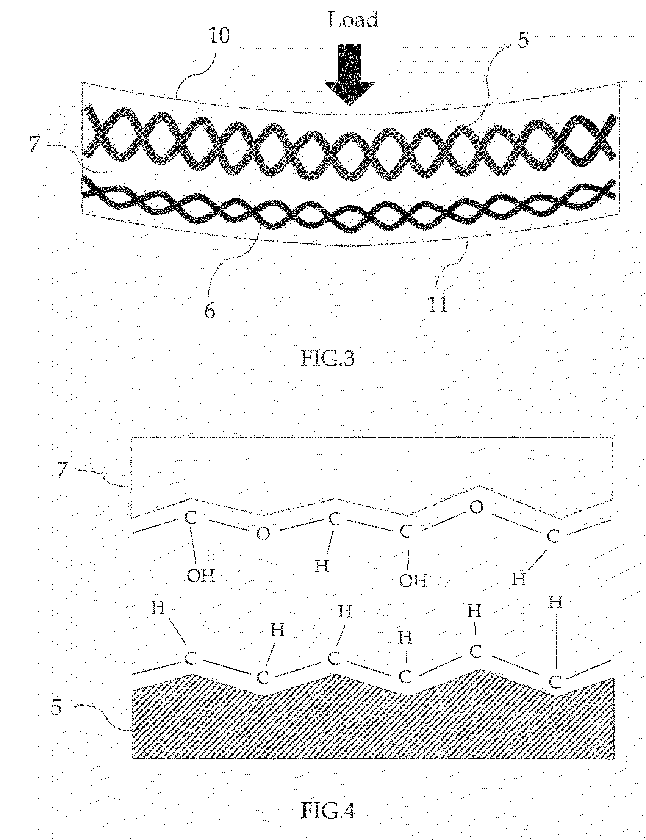
FIG. 6 is an enlarged cross sectional view illustrating a part of a radome 1 according to this embodiment. Since the essential parts of the radome 1 of this embodiment are the same as those of the radome 1 of Embodiment 1, only different parts from those of the radome 1 of Embodiment 1 will be described. In FIG. 6, the radome 1 is formed of a substance in which the olefin woven material 5 and the glass cloth 6 have been impregnated with the matrix resin 7 and are integrated with each other. Two pieces of glass cloth 6 are disposed at the outer side and at the inner side of the radome respectively. Between the two pieces of glass cloth 6, the olefin woven material 5 is disposed. A portion where the olefin woven material 5 has been impregnated with the matrix resin 7 forms the olefin woven material-containing area layer 8, and a portion where the glass cloth 6 has been impregnated with the matrix resin 7 forms the glass cloth-containing area layer 9. Further, the outside environment i...

example 1

NE-Glass (glass cloth, thickness: 0.16 mm) was disposed in an inner mold, and a woven material (olefin woven material, thickness: 0.63 mm) using an ultrahigh molecular weight polyethylene fiber was laminated thereon. Next, the NE-Glass and the woven material were covered with a mold releasing film, and the space between the periphery part of the mold releasing film and the inner mold was sealed in such a manner as to maintain airtightness. Thereafter, a mixture of vinyl ester resin (matrix resin, Repoxy R7070, manufactured by Showa High Polymer Co., Ltd.) and a curing agent (organic peroxide, PERMEK N, manufactured by NOF CORPORATION) was injected in the inner mold through a resin inlet port preformed on the inner mold while evacuating the space between the mold releasing film and the inner mold for impregnation. Here, 1 part by weight of the curing agent was used based on 100 parts by weight of vinyl ester resin. Next, the resultant was heated at 100° C. for 120 minutes to cure the...


PUM

PropertyMeasurementUnit
dielectric constantaaaaaaaaaa

Abstract

The present invention relates to a radome which has excellent transmission loss of radio waves and structural strength, which can be easily produced, and which has favorable workability, and a method of producing the same. The radome includes an olefin woven material and a glass cloth, in which the olefin woven material and the glass cloth are impregnated with a matrix resin to be integrated with each other, and the glass cloth is disposed closer to an inner side of the radome than the olefin woven material. As the olefin woven material, a woven material formed of an ultrahigh molecular weight polyethylene fiber can be used. As the matrix resin, an epoxy resin, a vinyl ester resin, an unsaturated polyester resin, or a silicone resin can be used.

Description

BACKGROUND OF THE INVENTION1. Field of the InventionThe present invention relates to a radome for protecting a radio wave device from the outside environment, and a method of producing the same. More particularly, the present invention relates to a radome for use in aircraft, vehicles, etc., and a method of producing the same.2. Description of the Related ArtRadomes must not block the radio waves to be received, transmitted, or received / transmitted by a radio wave device and must have the structural strength required to protect the radio wave device from the outside environment. Mentioned as a conventional radome having such properties there are radomes using a composite material having reinforced fiber in a matrix resin, i.e., a single layer panel formed of a fiber reinforced plastic. Moreover, there are also radomes using sandwich structure panels in which a core formed of a low density dielectric such as a foamed body is sandwiched between a first composite material facing having...

Claims


Application Information

Patent Timeline
Patent Type & Authority Patents(United States)
IPC IPC(8): B60R21/16
CPCH01Q1/422Y10T442/259Y10T442/291Y10T442/30Y10T442/3528Y10T428/13Y10T428/1362Y10T428/2495Y10T428/1352Y10T428/239Y10T156/1092
Inventor UTSUMI, SHIGERUMURAKAMI, MUNEOKANEKO, KIMIHIROKUMADA, TERUHIKO
Owner MITSUBISHI ELECTRIC CORP
Why Eureka
Try Eureka