Low common-mode voltage control method and system for three-level converter

A common-mode voltage and control method technology, applied in the direction of converting AC power input to DC power output, electrical components, output power conversion devices, etc., can solve the problem of large output current waveform ripple, reduced service life of devices, and increased system loss etc. to achieve the effect of reducing output current ripple, reducing current ripple, and reducing switching loss

Active Publication Date: 2019-09-17
SHANDONG UNIV
View PDF2 Cites 6 Cited by
  • Summary
  • Abstract
  • Description
  • Claims
  • Application Information

AI Technical Summary

Problems solved by technology

The inventor found in the research and development process that the above modulation method only uses part of the space vector to modulate the reference voltage vector. Compared with the traditional space vector modulation method, the ripple of the output current waveform is extremely large, which increases the system loss and reduces the service life of the device.

Method used


Image

  • Low common-mode voltage control method and system for three-level converter
  • Low common-mode voltage control method and system for three-level converter
  • Low common-mode voltage control method and system for three-level converter

Examples


Embodiment 1

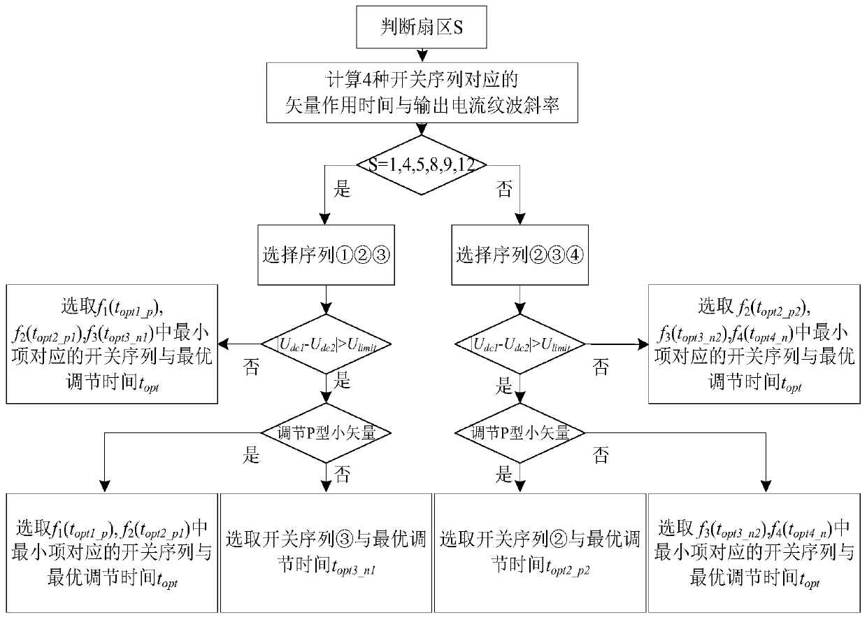
[0048] This embodiment provides a low common-mode voltage control method for a three-level converter based on optimal output current ripple, which uses nineteen vectors in the three-level space vector modulation method to synthesize a reference voltage vector, and The action time when solving the optimal ripple of each basic vector makes the common-mode voltage drop of the converter one-sixth of the DC bus voltage, and significantly improves the power quality of the output current while having the active controllability of the midpoint potential.

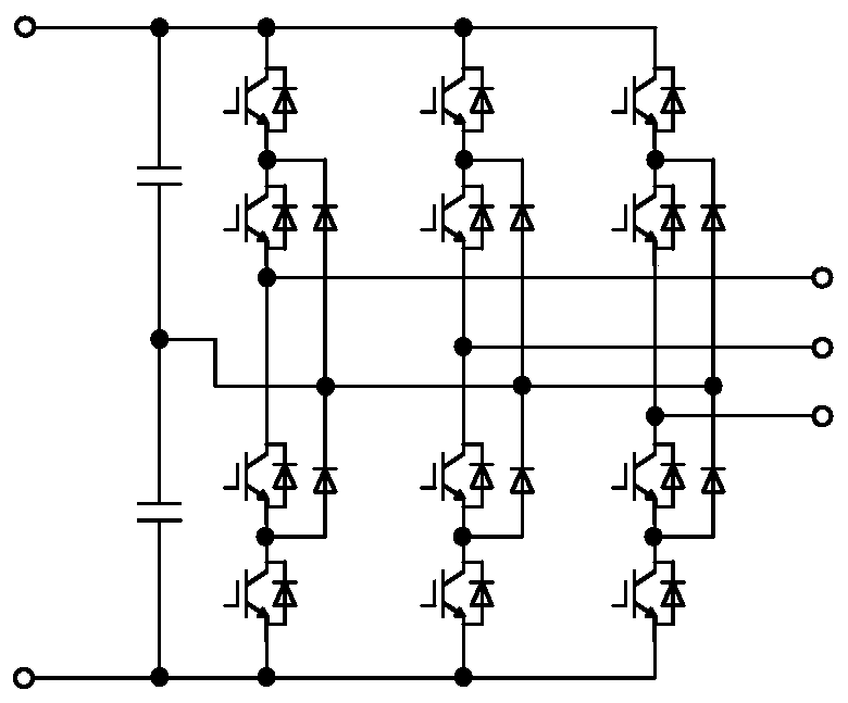
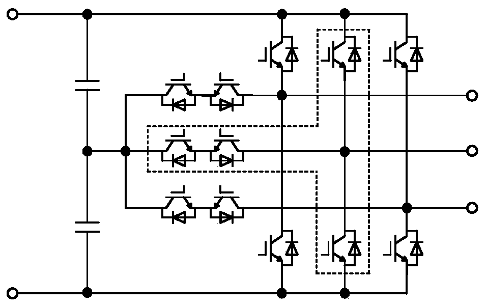
[0049] The topology of a typical three-level converter is shown in Figure 1(a) and Figure 1(b), where Figure 1(a) is a pole-clamped three-level converter, and (b) is a T type three-level converter; this topology is characterized by three-phase three-level, and each phase bridge arm includes four power switch tubes (insulated gate bipolar transistor (IGBT) or other forms of transistors), and its DC side includes Two filter capacitors...

Embodiment 2

[0129] This embodiment provides a low common-mode voltage control system for a three-level converter, which includes:

[0130] The sector number judging module is used to draw the space vector diagram, divide the space vector diagram into multiple sectors, and judge the sector number according to the size relationship between the three-phase reference voltages;

[0131] The switching sequence design module is used to select a plurality of basic voltage vectors from the sector where the reference voltage vector is located to construct various switching sequences;

[0132] The action time calculation module is used to calculate the action time of each basic voltage vector in each switching sequence;

[0133] The current ripple slope calculation module is used to calculate the output current ripple slope of each basic voltage vector in each switching sequence;

[0134] The action time modification module is used to synchronously modify the action time of each basic voltage vecto...

Embodiment 3

[0138] This embodiment provides a computer-readable storage medium, on which a computer program is stored. When the program is executed by a processor, the steps in the method for controlling the low common-mode voltage of a three-level converter as shown in FIG. 1 are implemented.


PUM


Abstract

The invention discloses a low common-mode voltage control method and system for a three-level converter. The method comprises the following steps: drawing a space vector diagram, dividing the space vector diagram into a plurality of sectors, and judging the number of the sectors according to the size relation between three-phase reference voltages; selecting a plurality of basic voltage vectors from a sector where the reference voltage vector is located, and constructing a plurality of switch sequences; calculating the action time and the output current ripple slope of each basic voltage vector in each switch sequence; synchronously modifying the action time of each basic voltage vector in each switch sequence to obtain the action time of each modified basic voltage vector in each switch sequence; combining the output current ripple slope of each basic voltage vector in each switch sequence with the modified action time to determine the switch sequence enabling the output current ripple to be minimum and the optimal adjustment time; and controlling the three-level converter by using the determined switch sequence and the optimal adjustment time.

Description

technical field [0001] The present disclosure relates to the technical field of converter control, in particular to a low common-mode voltage control method and system for a three-level converter based on optimal output current ripple. Background technique [0002] Compared with two-level converters, three-level converters subject devices to less switching stress and can significantly improve the output waveform. In the typical three-level converter topology, diode-clamped three-level converters and T-type three-level converters have been widely used in new energy power generation and power quality control. However, the converter will inevitably be accompanied by a large-scale common-mode voltage when it is working, and the common-mode voltage will cause overvoltage to the motor bearing in the motor drive system, which will greatly damage the motor; at the same time, the common-mode voltage with high frequency changes It will generate great electromagnetic interference, cau...

Claims


Application Information

Patent Timeline
Patent Type & Authority Applications(China)
IPC IPC(8): H02M7/483H02M1/12
CPCH02M1/12H02M7/483H02M1/123
Inventor 张承慧刘玺邢相洋秦昌伟胡顺全
Owner SHANDONG UNIV
Why Eureka
Try Eureka