Vacuum food processor convenient to clean

A food processing machine and vacuum technology, which is applied in the field of food processing, can solve the problems of complicated cleaning, many vacuum pipelines, and the cup lid cannot be soaked and washed, and achieve the effects of simplifying the vacuuming pipeline, improving the vacuuming efficiency, and improving the reliability

Inactive Publication Date: 2019-09-20
JOYOUNG CO LTD
View PDF11 Cites 1 Cited by
  • Summary
  • Abstract
  • Description
  • Claims
  • Application Information

AI Technical Summary

Problems solved by technology

The air pump of the existing vacuum device is generally installed in the machine base or in the cup cover. When the air pump is installed in the machine base, it is often necessary to transfer the machine base and the cup holder of the stirring cup once, and then connect the cup body and the cup. The air pump can be connected to the inside of the cup body only after the cover is transferred twice, which will result in many vacuum pipelines, many interfaces, high cost, high risk of air leakage in the vacuum device, and low vacuum reliability. When the air pump is installed on the cup cover It will cause the cup cover to be unable to be soaked and washed, the cleaning is complicated, and the user experience is poor

Method used


Image

  • Vacuum food processor convenient to clean
  • Vacuum food processor convenient to clean
  • Vacuum food processor convenient to clean

Examples


Embodiment 1

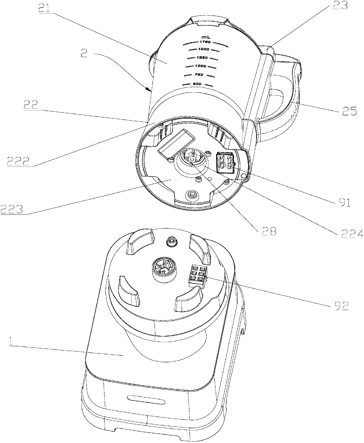
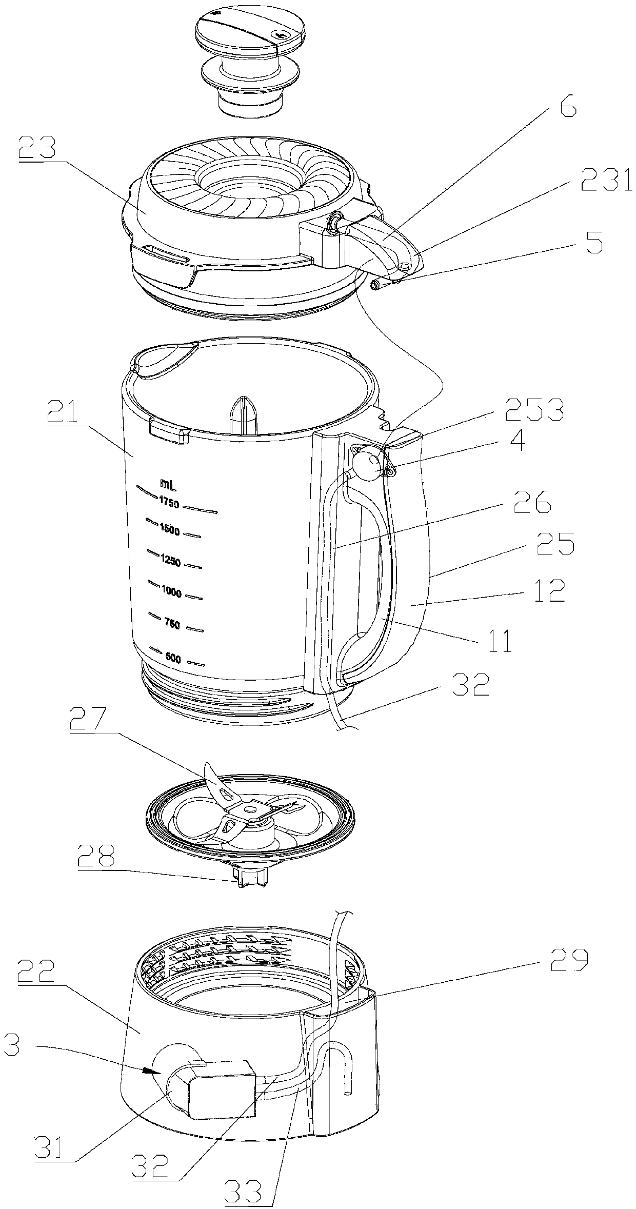
[0036] Such as Figure 1 to Figure 3 As shown, the vacuum food processor of this embodiment includes a machine base 1 , a stirring cup 2 and a vacuum device 3 . The base 1 is provided with a motor and a main circuit board (not shown). The stirring cup 2 is located above the machine base 1. The stirring cup 2 includes a cup body 21, a cup holder 22 and a cup cover 23. The cup body 21 is a glass cup body, the cup holder 22 is a plastic cup holder, and the cup cover 23 is a plastic cup cover. The body 21 has an upper opening and a lower opening. The cup holder 22 is threadedly connected to the lower opening of the cup body 21. The cup cover 23 is disassembled and installed on the upper opening of the cup body 21. The cup cover 23 is provided with a communication hole communicating with the inside of the cup body 21. One side of the cup body 21 is provided with a handle 24, the handle 24 is integrally formed with the cup body 21, the handle 24 is provided with a handle cover 25, ...

Embodiment 2

[0047] The difference between this embodiment and Embodiment 1 lies in the structure of the handle cover, combined with Figure 4 to Figure 6 As shown, the handle cover 25 of this embodiment includes a left handle cover 251 and a right handle cover 252, the left handle cover 251 and the right handle cover 252 are snapped together to form the handle cover 25, and the upper end of the handle cover 25 is provided with a first adapter mounting cavity 253, the first adapter 4 is located in the first adapter installation cavity 253, the upper part of the left handle cover 251 and the upper part of the right handle cover 252 enclose the aforementioned first adapter installation cavity 253, the lower part of the left handle cover 251 and the lower part of the right handle cover 252 The handle cavity 254 for accommodating the handle 24 is formed by enclosing it, so that the first adapter mounting cavity 253 is arranged above the handle cavity 254, on the one hand, avoiding interference ...

Embodiment 3

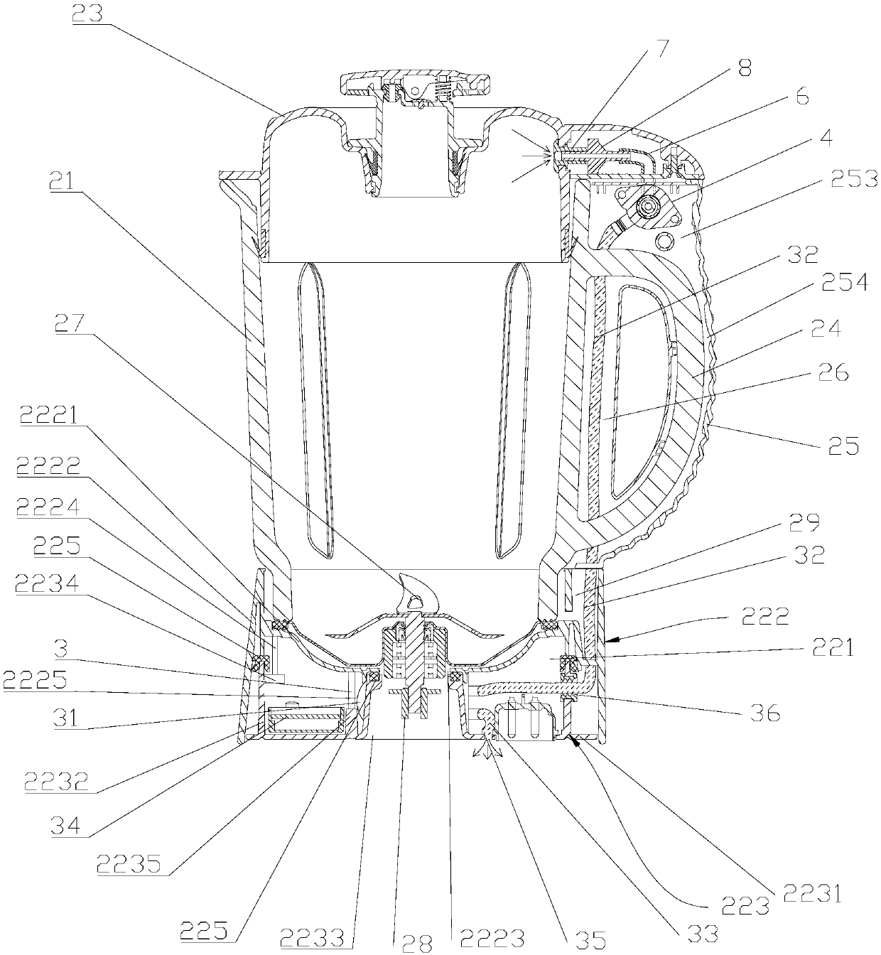
[0058] The difference between this embodiment and Embodiment 1 and Embodiment 2 lies in the sealed cavity structure of the cup holder, combined with Figure 7 As shown, the air pump 31 of this embodiment is placed in the sealed cavity 221, so that the height requirement for the sealed cavity 221 is relatively low, and the height of the sealed cavity 221 will not be too large to cause the overall imbalance of the mixing cup. The air pump 31 includes a pump body 311 and motor 312, the suction pipe 32 and the exhaust pipe 33 are all connected to the pump body 311, the air pump circuit board 34 is electrically connected to the motor 312, and the air pump circuit board 34 is also located in the sealed cavity 221, the pump body 311 is connected to the motor 312 Being fixed in an L shape makes the fixing positions of the pump body 311 and the motor 312 in the sealing chamber 221 reasonable and compact, and also makes the piping system take up less space and the piping stroke is effect...


PUM


Abstract

The invention discloses a vacuum food processor convenient to clean. The vacuum food processor comprises a vacuumizing device, a processor base, a stirring cup and a smashing cutter; and the stirring cup comprises a cup body, a cup base and a cup cover, the cup cover is provided with a communicating hole communicating with the interior of the cup body, a handle and a handle cover are arranged on one side of the cup body, the vacuumizing device comprises an air pump, an air suction pipe, an air exhaust pipe and an air pump circuit board, the cup base is provided with a sealing cavity, the air pump is arranged in the sealing cavity, a first interlayer is arranged between the handle cover and the side wall of the cup body, the first interlayer downwards extends to the sealing cavity, a first transferring head is arranged on the handle cover, the cup cover is provided with a second transferring head communicating with the communicating hole, one end of the air suction pipe is connected with the air pump, the other end of the air suction pipe extends out of the cup base and then extends upwards along the first interlayer to be connected to the first transferring head, and the second transferring head is in inserted-connection fit with the first transferring head. According to the vacuum food processor, a user can conveniently clean the overall stirring cup.

Description

technical field [0001] The invention belongs to the field of food processing, in particular to a vacuum food processing machine which is easy to clean. Background technique [0002] Existing vacuum food processing machines usually include a machine base, a stirring cup and a vacuuming device for vacuumizing the stirring cup. Exhaust pipe and air pump circuit board, the air pump communicates with the outside world through the exhaust pipe, and the air pump communicates with the inside of the cup body through the suction pipe. During the working process, the air pump circuit board controls the air pump to vacuum the inside of the cup body to prevent Foodstuffs are oxidized resulting in nutrient loss. The air pump of the existing vacuum device is generally installed in the machine base or in the cup cover. When the air pump is installed in the machine base, it is often necessary to transfer the machine base and the cup holder of the stirring cup once, and then connect the cup ...

Claims


Application Information

Patent Timeline
Patent Type & Authority Applications(China)
IPC IPC(8): A47J43/07A47J43/046
CPCA47J43/046A47J43/0716A47J43/0722
Inventor 王旭宁杨开清张玉印
Owner JOYOUNG CO LTD
Why Eureka
Try Eureka