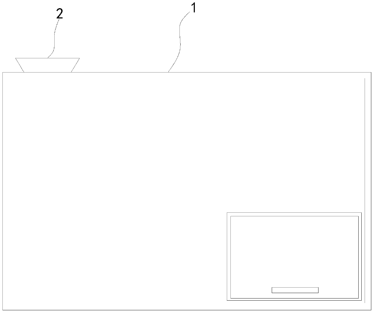
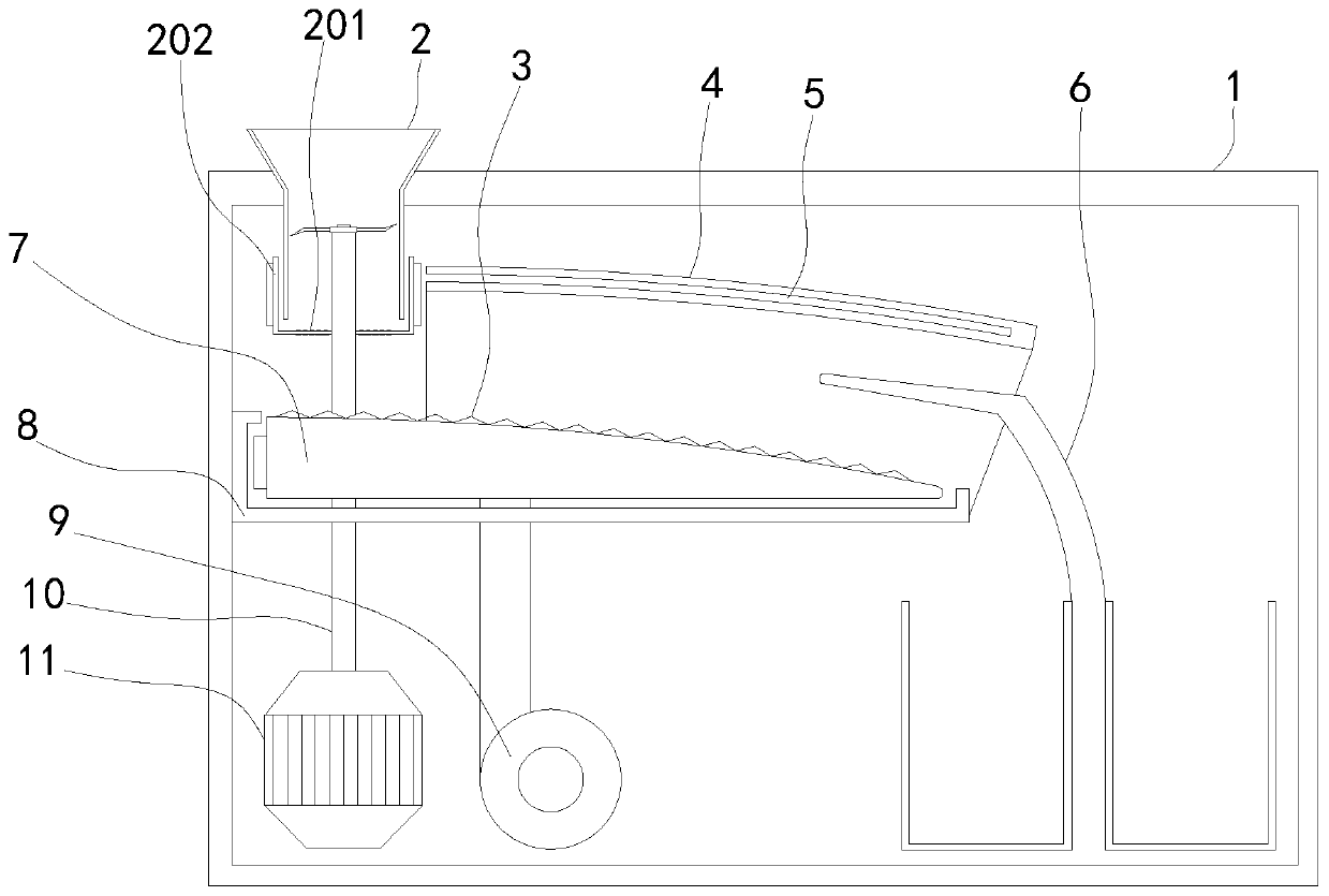
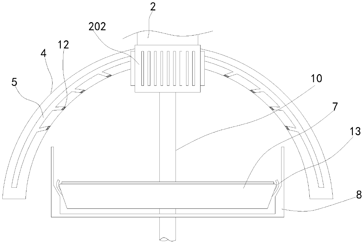
[0026] see Figures 1 to 8 , a schematic diagram of the planar structure and a schematic diagram of the three-dimensional structure of a device for sorting and recycling soundproof waste cotton waste.
[0027] A device for sorting and recovering sound-insulating waste cotton and waste, comprising a device main body 1 and a feeding channel 2. A vibrating plate 7 is fixedly connected to the inside of the device main body 1, and a dust cover 4 is fixedly installed on the right side of the material feeding channel 2.
[0028] In a specific implementation, a motor 11 is movably installed on the lower end of the main body 1 of the device, and a rotating rod 201 is fixedly connected to the upper end of the motor 11. The two ends of the rotating rod 201 are fixedly connected to a rotating layer 202 and the rotating layer 202 is sleeved on the outside of the feeding channel 2, so that The motor 11 can drive the rotating layer 202 to rotate through the rotating rod 201 while driving the crushing knife to crush the soundproof cotton.
[0029] In a specific implementation, the left side of the dust cover 4 is close to the rotating layer 202, the inside of the dust cover 4 is provided with an air suction channel 5 and the dust cover 4 is arranged in a semicircular arc as a whole, and the lower end of the air suction channel 5 is arranged in an inclined arc and is fixedly installed. There is a filter screen 12, so that the rotating layer 202 can generate a slight negative pressure in the suction channel 5, so that the dust generated when the sound insulation cotton fragments are separated can be adsorbed to the top through the suction channel 5 for preliminary dust treatment, and through The arc shape of the suction duct 5 makes the dust on the filter screen 12 blown down by the airflow behind and leaves the vibrating plate 7 from the two ends of the dust cover 4 .
[0030] In the specific implementation, the upper end of the vibrating plate 7 is fixedly connected to the limit bump 3 and the upper end is set in an outwardly convex arc shape. The vibrating plate 7 is provided with a moving cavity 16 and the rotating rod 10 runs through the moving cavity 16. The rotating rod 10 and the moving cavity 16 The upper part is fixedly connected with the occlusal vibrating block 18 with the same setting and the occlusal vibrating bump 18 is set at a triangular obtuse angle, so that when the sound-insulating cotton is at the left end of the vibrating plate 7, the radian is small so that its moving speed to the right is relatively slow so that the sound-insulating cotton can be compared. Meticulous separation improves the separation efficiency of sound insulation cotton.
[0031] In the specific implementation, the moving cavity 16 is fixedly connected with an engaging protrusion 1601, and the middle end of the rotating rod 10 is provided with a moving groove 17, and the moving groove 17 is arranged in a curved wave, so that the motor 11 can drive the crushing knife to crush the soundproof cotton. Drive the vibrating plate 7 of the internal occlusal moving groove 17 to move up and down, so that the fragments of sound-proof cotton are vacated up and down under the action of the vibrating plate 7, so that the sound-proof cotton with a larger mass and a shorter vertical movement distance is in the lower layer and has a lighter weight. The larger sound insulation cotton is on the upper layer to achieve the effect of preliminary separation.
[0032] In specific implementation, air jet pipes 13 are fixedly connected to the front and rear sides of the vibrating plate 7, and the upper end of the air jet pipe 13 is arranged in an arc shape towards the inner side of the vibrating plate 7, so that when the vibrating plate 7 is separated from the soundproof cotton, it can pass through the air flow to make the air of different qualities The up and down movement distance of the sound insulation cotton is further increased, which improves the separation efficiency.
[0033] In a specific implementation, the upper end of the air injection pipe 13 is fixedly connected with an air injection port 19, and the air injection port 19 is a long circular arc shape protruding from the upper and lower ends and has a trapezoidal notch on the edge, so that the air injection of the air injection pipe 13 has a wider lateral range. At the same time, the range is larger to further improve the efficiency of jet separation.
[0034] In the specific implementation, the right end of the vibrating plate 7 is fixedly equipped with a material distribution plate 6, and the upper end of the material distribution plate 6 is set straight and the lower end is set as an arc, so that the separated sound insulation cotton fragments can be more conveniently divided into two parts. At the same time, it is more convenient to enter the receiving box through the curved surface. .
[0035] The working principle of a kind of sound insulation waste cotton waste sorting recovery device of the present invention is as follows.
[0036]First, start the motor 11, and then put different types of sound-proof cotton into the material channel 2. The motor 11 drives the damaged knife through the rotating rod 10 to crush the sound-proof cotton. The set moving groove 17 enables the motor 11 to drive the crushing knife to break the sound-proof cotton, and at the same time, it can drive the vibrating plate 7 that engages the moving groove 17 to move up and down, so that the sound-proof cotton fragments are vacated up and down under the action of the vibrating plate 7, so that the quality is relatively high. The sound insulation cotton with a relatively short moving distance up and down is on the lower layer, and the sound insulation cotton with a relatively large moving distance up and down is on the upper layer, which achieves the effect of preliminary separation. The set limit bump 3 makes the soundproof cotton move slowly to the right because of the small radian at the left end of the vibrating plate 7, so that the soundproof cotton can be separated more carefully to improve the separation efficiency of the soundproof cotton, and then through the vibrating plate 7. On the moving chamber 16 and the rotating rod 10, there are triangular obtuse-angled occlusal vibration bumps 18 with the same arrangement, so that the moving plate 7 can generate vibration while moving up and down, thereby further improving the separation efficiency of the sound insulation cotton, and then through the vibration The vibrating cavity 15 provided in the plate 7 and the octagonal vibrating block 14 inside make the vibrating plate 7 contact with the thorns 1501 through the edges and corners of the vibrating block 14 to further improve the vibration efficiency and achieve the purpose of further improving the separation efficiency. The air jet pipe 13 installed at the front and rear ends of the vibrating plate 7 and the upper end of the air jet pipe 13 is arranged in an arc shape towards the inner side of the vibrating plate 7, so that the vibrating plate 4 separates the sound insulation cotton and can pass through the airflow generated by the fan 9 when the sound insulation cotton is vacated to make different quality sound insulation The up and down movement distance of the cotton is further increased, so that the separation efficiency is improved, and then the front and rear sides of the vibration plate 4 are inwardly inclined and are parallel to the inward inclination of both sides of the lower end of the fixed plate 8, so that when the vibration plate 7 moves upwards The air injection pipe 13 can normally inject air, but when it moves downward, it will be squeezed so that it cannot inject air, so that the distance between the sound insulation cotton with different qualities is getting farther and farther, thereby further improving the separation efficiency of the sound insulation cotton. The upper and lower ends of the trachea 13 are protruding in a long arc shape and the edge is provided with a trapezoidal notch air injection port 19, which makes the lateral range of the air injection of the air injection pipe wider and at the same time, the range is larger, thereby further improving the efficiency of air injection separation, and then through the whole The dust cover 4 that is provided with semi-circular arc and the lower end of the air suction duct 5 in it is provided with an inclined arc and is fixedly installed with a filter screen 12, so that the motor 11 can drive the rotating layer 202 to rotate through the rotating rod 201, so that it can be rotated in the air suction. A slight negative pressure is generated in channel 5, so that the dust generated when the soundproof cotton fragments are separated can be absorbed to the top through the suction channel 5, and the dust on the filter will be blown by the airflow behind through the arc of the suction channel 5 Leave the vibrating plate 7 from the two ends of the dust cover 4, so as to achieve the effect of removing dust. Finally, the right end of the vibrating plate 7 is fixedly installed with the upper end being straight and the lower end being arc-shaped. The fragments can be more conveniently divided into two parts, and at the same time enter the receiving box more conveniently through the curved surface to complete the separation and recovery of the sound insulation cotton .