Annular conveying mechanism for assembling cylindrical lithium ion battery cap assembly

A technology of lithium-ion battery and circular transportation, which is applied in the direction of battery pack parts, battery cover/end cover, electrical components, etc. It can solve the problems of low efficiency, easy deviation, time-consuming and labor-intensive manual transmission, etc., and achieve good compatibility and Coordination, stable and reliable positioning force, and the effect of improving assembly efficiency

Pending Publication Date: 2019-09-20
伊欧激光科技(苏州)有限公司
View PDF0 Cites 0 Cited by
  • Summary
  • Abstract
  • Description
  • Claims
  • Application Information

AI Technical Summary

Problems solved by technology

[0004] 1) The transfer of cap components between stations lacks reliable and effective conveying equipment. At present, it is still mainly done manually, but manual transfer is time-consuming and labor-intensive, which is not only inefficient, but also prone to deviations, resulting in production stagnation
[0005] 2) There is a lack of good transfer carriers for the cap components, and the transfer carriers between different stations are often replaced, which cannot be well matched and adapted to each station equipment, resulting in poor positioning stability for the cap components and matching accuracy during assembly Not high, yield rate drops
[0006] Obviously, the existence of the above problems has greatly hindered the development and application of the current assembly process of cap components by cylindrical lithium-ion battery cap manufacturers.

Method used


Image

  • Annular conveying mechanism for assembling cylindrical lithium ion battery cap assembly
  • Annular conveying mechanism for assembling cylindrical lithium ion battery cap assembly
  • Annular conveying mechanism for assembling cylindrical lithium ion battery cap assembly

Examples


Embodiment

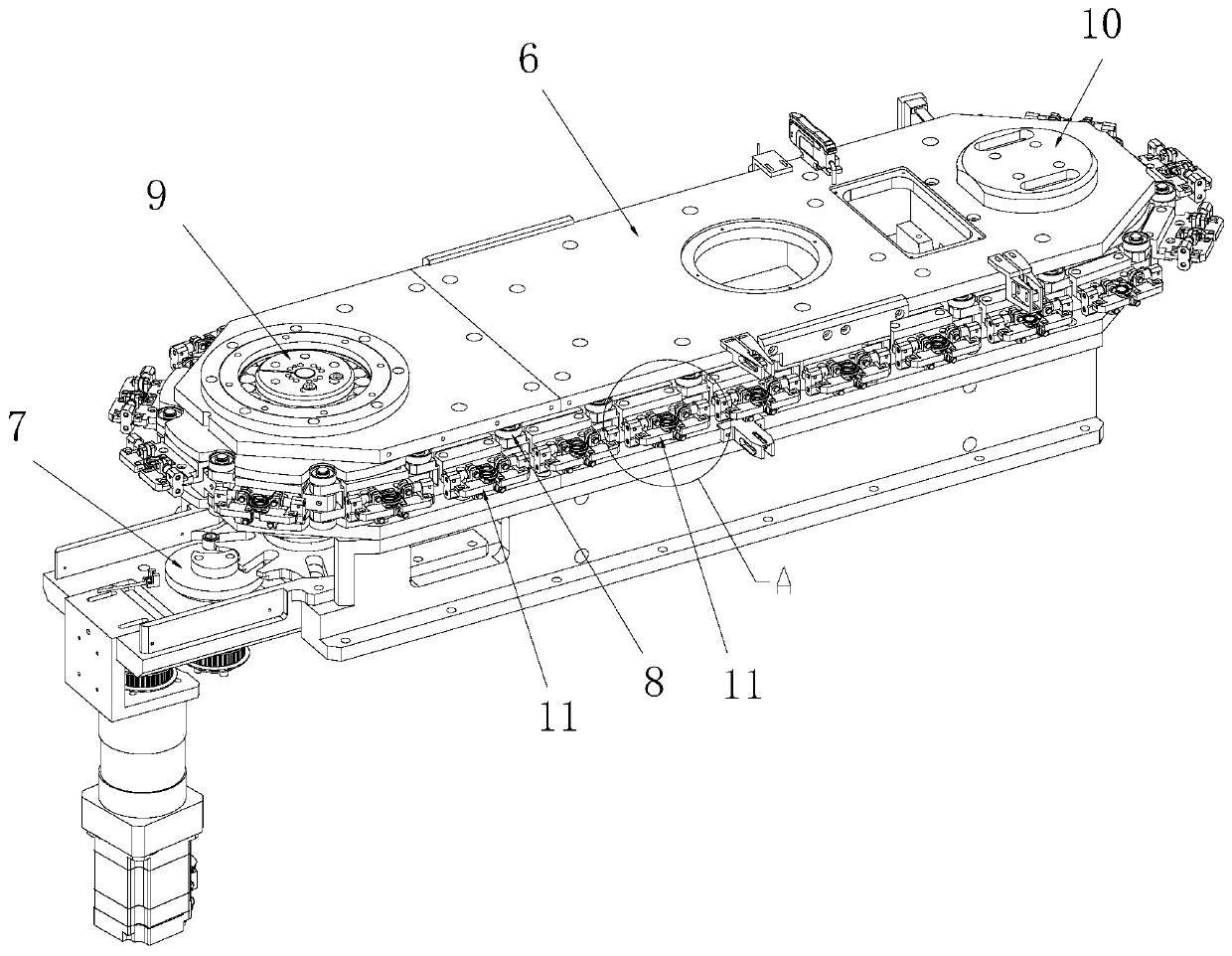
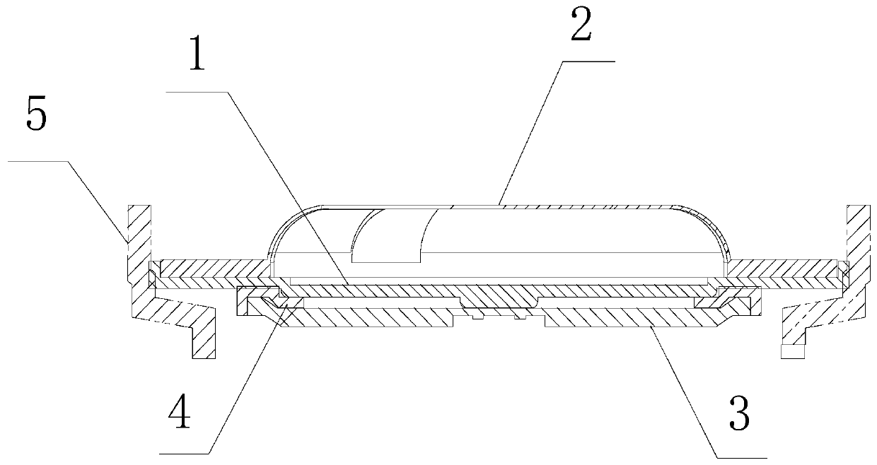
[0026] Example: Combine figure 1 with figure 2 As shown, it is a specific embodiment of the annular conveying mechanism for the assembly of the cylindrical lithium-ion battery cap assembly of the present invention, which is specially used for conveying such as image 3 Components of the cylindrical Li-ion battery cap shown.

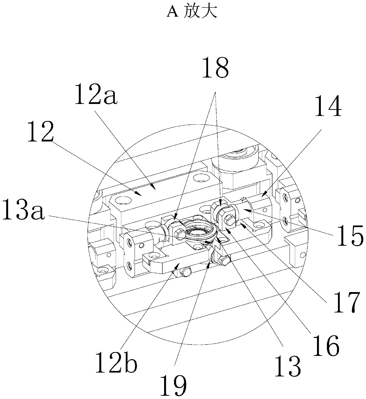
[0027] This mechanism has machine platform 6, and machine platform 6 is provided with servomotor index plate 7, transmission sprocket group and the annular transmission chain 8 that is tensioned by transmission chain wheel group, and transmission chain wheel group is arranged on machine platform 6 The driving sprocket 9, the driven sprocket 10 and some tensioning sprockets (not visible in the figure), the servo motor indexing plate 7 is connected with the driving sprocket 9. Such as figure 1 As shown, the transmission chain 8 in this embodiment is arranged in an oval shape. At the same time, another core design of the present invention is that a plu...


PUM


Abstract

The invention discloses an annular conveying mechanism for assembling a cylindrical lithium ion battery cap assembly. The annular conveying mechanism comprises a machine table, and is characterized in that a servo motor indexing plate, a transmission chain wheel set and an annular transmission chain which is tensioned by the transmission chain wheel set are arranged on the machine table; the transmission chain wheel set comprises a driving chain wheel, a driven chain wheel and a plurality of tensioning chain wheels, wherein the driving chain wheel, the driven chain wheel and the plurality of tensioning chain wheels are arranged on the machine table, and the servo motor indexing plate is connected with the driving chain wheel; and the annular conveying mechanism further comprises a plurality of elastic clamping mechanisms which are uniformly fixed to the transmission chain at intervals and are used for clamping the cap assembly, the elastic clamping mechanisms comprise positioning plates, cap assembly positioning holes and two spring clamping block devices, wherein the cap assembly positioning holes are formed in the positioning plates, the two spring clamping block devices are symmetrically arranged on the left and right sides of the cap assembly positioning holes, and are used for clamping the cap assembly, and the cap assembly positioning holes are internally provided with concave tables for bearing the cap assembly. The annular conveying mechanism can take place of manual work to reliably convey the cap assembly among assembly working positions, the efficiency is improved, the cap assembly positioning stability is high, and the transmission precision is high.

Description

technical field [0001] The invention relates to an annular conveying mechanism for assembling a cap assembly of a cylindrical lithium ion battery. Background technique [0002] It is generally known in the industry that the cap is the core component of the cylindrical lithium-ion battery, which is related to the safety of the cylindrical lithium-ion battery. At present, the caps of cylindrical lithium-ion batteries widely sold on the market are usually composed of explosion-proof plate 1, top cover 2, orifice plate 3 (aluminum plate), orifice plate gasket 4 and sealing ring 5. The details are as follows: image 3 As shown, the assembly relationship of these five components is: the top cover 2 is welded and fixed on the top surface of the explosion-proof disk 1, the orifice gasket 4 is placed on the bottom surface of the explosion-proof disk 1, the orifice plate 3 is placed on the orifice gasket 4 and connected with the explosion-proof disk 1, the bottom surface is welded, an...

Claims


Application Information

Patent Timeline
IPC IPC(8): B23K26/21B23K26/70H01M2/04H01M10/0525
CPCB23K26/21H01M10/0525B23K26/702H01M50/147Y02E60/10
Inventor 成奎栋崔伦硕金秀洪李智晶
Owner 伊欧激光科技(苏州)有限公司
Why Eureka
Try Eureka