Supergravity environmental stroke adjusting method and device

A super-gravity, stroke technology, applied in the direction of fluid pressure actuation device, fluid pressure converter, mechanical equipment, etc., can solve the problems of non-adjustment and inconvenient stroke control.

Pending Publication Date: 2019-09-20
NANJING SHUANG HUAN ELECTRIC APPLIANCE SHEA CO LTD
View PDF0 Cites 2 Cited by
  • Summary
  • Abstract
  • Description
  • Claims
  • Application Information

AI Technical Summary

Problems solved by technology

[0003] The purpose of the present invention is to invent a method and device for stroke adjustment in a supergravity environment, aiming at the problem that the stroke control in the existing supergravity environment is inconvenient and cannot be adjusted.

Method used


Image

  • Supergravity environmental stroke adjusting method and device
  • Supergravity environmental stroke adjusting method and device
  • Supergravity environmental stroke adjusting method and device

Examples


Embodiment 1

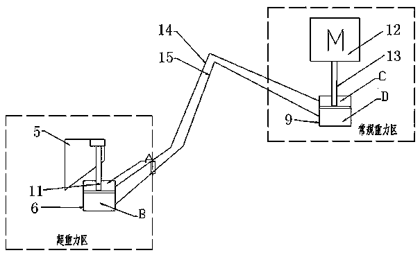
[0028] like figure 1 shown.

[0029] A stroke adjustment method in a supergravity environment, first of all, the driving block 5 in the supergravity state is connected to the piston rod 11 of the supergravity hydraulic cylinder 6 installed on the supergravity driving device, and the supergravity hydraulic cylinder 6 is controlled by Conventional gravity hydraulic cylinder 9 in conventional gravity hydraulic device, such as figure 1 As shown, the adjustment of the stroke of the piston rod 11 is realized by controlling the pressure difference between the rod cavity and the rodless cavity of the supergravity hydraulic cylinder 6, and then the stroke of the driving block 5 is adjusted and finally the stroke of the movable push plate in the material box is adjusted. The rod chamber of the conventional hydraulic cylinder of the conventional gravity hydraulic device is connected with the rod chamber of the supergravity hydraulic cylinder, and the rodless chamber of the conventional ...

Embodiment 2

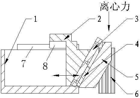
[0031] like figure 2 shown.

[0032] A stroke adjustment device in a supergravity environment, which includes a material box 1 installed on a hanging basket of a supergravity rotating device, and one side of the material box 1 is provided with a transparent window 10 for observation. A push pedal guide rail 7 is installed on the material box 1, and a push pedal slider 8 is installed on the push pedal guide rail 7, and the push pedal slider 8 is fixedly connected with a movable push pedal 2, and the movable push pedal 2 is inserted into the material box 1, the described A driving guide rail 3 is fixedly installed on the inclined side of the movable push plate 2, and the driving guide rail 3 is equipped with a driving slider 4, and the driving slider 4 is fixedly connected with the driving block 5, and the driving block 5 is connected with the piston rod of the supergravity hydraulic cylinder 6, The rod chamber and the rodless chamber of the supergravity hydraulic cylinder 6 a...

Embodiment 3

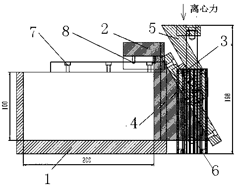
[0034] like Figure 3-5 shown.

[0035] A stroke adjustment device in a supergravity environment, its three-dimensional structure is as follows: Figure 5 As shown, it includes a material box 1 installed on the hanging basket of the supergravity rotating device, and one side of the material box 1 is provided with a transparent window 10 for observation ( Figure 4 ). A push pedal guide rail 7 is installed on the material box 1, and a push pedal slider 8 is installed on the push pedal guide rail 7, and the push pedal slider 8 is fixedly connected with a movable push pedal 2, and the movable push pedal 2 is inserted into the material box 1, the described A driving guide rail 3 is fixedly installed on the inclined side of the movable push plate 2, and the angle between the inclined side and the horizontal plane is greater than 90 degrees (135 degrees in the figure). The driving guide rail 3 is equipped with a driving slider 4, and the driving slider 4 and the driving block 5 a...


PUM


Abstract

The invention provides a supergravity environmental stroke adjusting method and device. The method is characterized in that a driving block in a supergravity state is connected to a piston rod of a supergravity hydraulic cylinder mounted on a supergravity driving device, wherein the supergravity hydraulic cylinder is controlled by a common gravity hydraulic device; the pressure difference between a rod port and a head port of the supergravity hydraulic cylinder is controlled to adjust the stroke of the piston rod, then the stroke of the driving block can be adjusted, and thus the stroke of a movable pushing plate in a material box can be adjusted. The method is simple, reliable, easy to carry out, and accurate to control.

Description

technical field [0001] The invention relates to a supergravity technology, in particular to a stroke adjustment technology in a supergravity state, in particular to a stroke adjustment method and device in a supergravity environment realized by hydraulic technology. Background technique [0002] The so-called supergravity refers to the force suffered by matter in an environment much greater than the earth's gravitational acceleration (9.8m / s2). The science of studying the process of physical and chemical changes in a hypergravity environment is called supergravity science, and the applied technology created by using the principles of supergravity science is called hypergravity technology. On Earth, an easy way to achieve a hypergravity environment is to simulate it by rotating to generate centrifugal force. Such rotating equipment is called a supergravity machine, also known as a rotating packed bed. When the supergravity machine is used in the gas-liquid multiphase proces...

Claims


Application Information

Patent Timeline
Patent Type & Authority Applications(China)
IPC IPC(8): F15B15/17F15B3/00
CPCF15B3/00F15B15/17
Inventor 吴林波魏华文储霄峰
Owner NANJING SHUANG HUAN ELECTRIC APPLIANCE SHEA CO LTD
Why Eureka
Try Eureka