
Imaging method and device based on spatial coding

An imaging method and spatial encoding technology, applied in image analysis, image data processing, instruments, etc., can solve the problems of low precision and slow modeling speed, and achieve the effect of high model precision, fast computing speed and short time

Active Publication Date: 2019-09-20
上海青燕和示科技有限公司
View PDF9 Cites 2 Cited by
  • Summary
  • Abstract
  • Description
  • Claims
  • Application Information

AI Technical Summary

Problems solved by technology

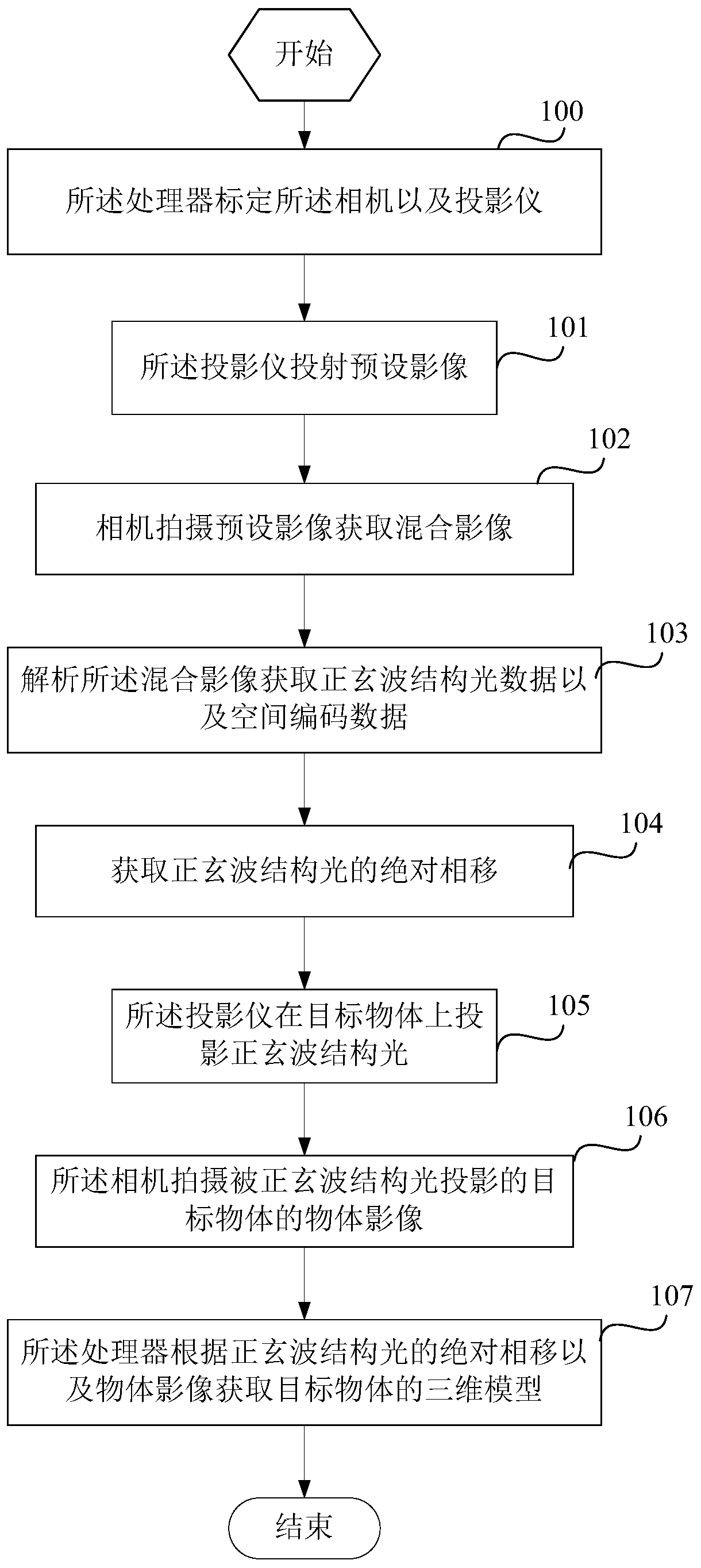
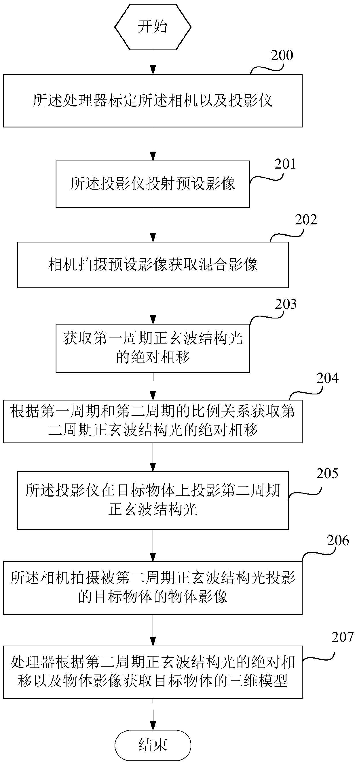
[0005] The technical problem to be solved by the present invention is to overcome the defects of slow modeling speed and low precision in the existing three-dimensional reconstruction of grating projection, and provide a , the imaging method and device based on spatial coding with the advantages of short time to acquire the model of the object and high model accuracy

Method used


Image

  • Imaging method and device based on spatial coding
  • Imaging method and device based on spatial coding

Examples


Embodiment 1

[0055] This embodiment provides an imaging device based on spatial coding, and the imaging device includes a camera, a projector, and a processor.

[0056] The projector is a color laser projector.

[0057] The processor includes a DLP LightCrafter 4500 development board manufactured by Texas Instruments Corporation.

[0058] The imaging device includes a housing, the camera and the projector are arranged in the housing, the camera includes a camera lens, the projector includes a projection lens, the camera lens and the projection lens and photographed on the front of the housing.

[0059] In this embodiment, the camera and the projector are integrated, but an independent camera and an independent projector can also be used to implement the imaging device of this embodiment by using a computer as a processor.

[0060] The processor is used to calibrate the camera and projector;

[0061] The projector is used to project a preset image, and the preset image projects a sine wa...


PUM


Abstract

The invention discloses an imaging method and device based on spatial coding, the imaging method is realized through an imaging device, the imaging device comprises a camera, a projector and a processor, the projector is a color laser projector, and the imaging method comprises the following steps: the processor calibrates the camera and the projector; wherein the projector projects a preset image, and the preset image respectively projects sine wave structured light and a spatial coding image through a monochromatic laser in the projector; analyzing the mixed image is analyzed to obtain sine wave structured light data and spatial coding data; the processor obtains the absolute phase shift of the sine wave structured light; wherein the projector projects sine wave structured light on a target object; the camera shoots an object image of the target object projected by the sine wave structured light; and the processor obtains a three-dimensional model of the target object according to the absolute phase shift of the sine wave structured light and the object image. The method has the advantages that the operation speed is high, the time for obtaining the model of the object is short, and the model precision is high.

Description

technical field [0001] The invention relates to an imaging method and device based on spatial coding. Background technique [0002] Three-dimensional reconstruction refers to the establishment of a mathematical model suitable for computer representation and processing of three-dimensional objects. It is the basis for processing, operating and analyzing its properties in a computer environment, and it is also a key technology for establishing a virtual reality that expresses the objective world in a computer. [0003] Three-dimensional reconstruction by grating projection is a three-dimensional reconstruction method. The grating is projected onto the reference plane and the surface of the measured object respectively. Since the reference plane is a horizontal plane, the reference grating projected on it will not be deformed; when the grating is projected onto the measured object When measuring the surface of an object, the grating will have different degrees of deformation, b...

Claims


Application Information

Patent Timeline
Patent Type & Authority Applications(China)
IPC IPC(8): G06T7/521G06T7/80
CPCG06T7/521G06T7/85
Inventor 袁丹寿
Owner 上海青燕和示科技有限公司
Learn More