
Z-direction flying focus scanning mode and image reconstruction method

A scanning method and image reconstruction technology, applied in the field of medical imaging, can solve the problems of inability to solve the reconstruction position, inconsistency, discontinuous reconstruction image layer thickness, etc., and achieve the effect of being conducive to the observation of non-transverse position

Active Publication Date: 2019-09-20
FMI MEDICAL SYST CO LTD
View PDF6 Cites 5 Cited by
  • Summary
  • Abstract
  • Description
  • Claims
  • Application Information

AI Technical Summary

Problems solved by technology

[0008] To sum up, the existing technology cannot solve the problem of discontinuous reconstruction positions and the problem of inconsistent layer thickness of reconstructed images everywhere.

Method used

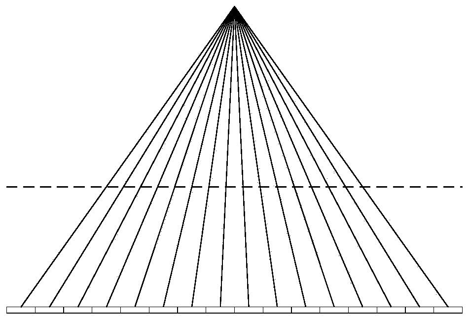

Image

  • Z-direction flying focus scanning mode and image reconstruction method
  • Z-direction flying focus scanning mode and image reconstruction method
  • Z-direction flying focus scanning mode and image reconstruction method

Examples


Embodiment Construction

[0040]In order to make the technical means of the present invention and the technical effects that can be achieved more clearly and more perfectly disclosed, the following embodiments are provided hereby, and the following detailed descriptions are made in conjunction with the accompanying drawings:

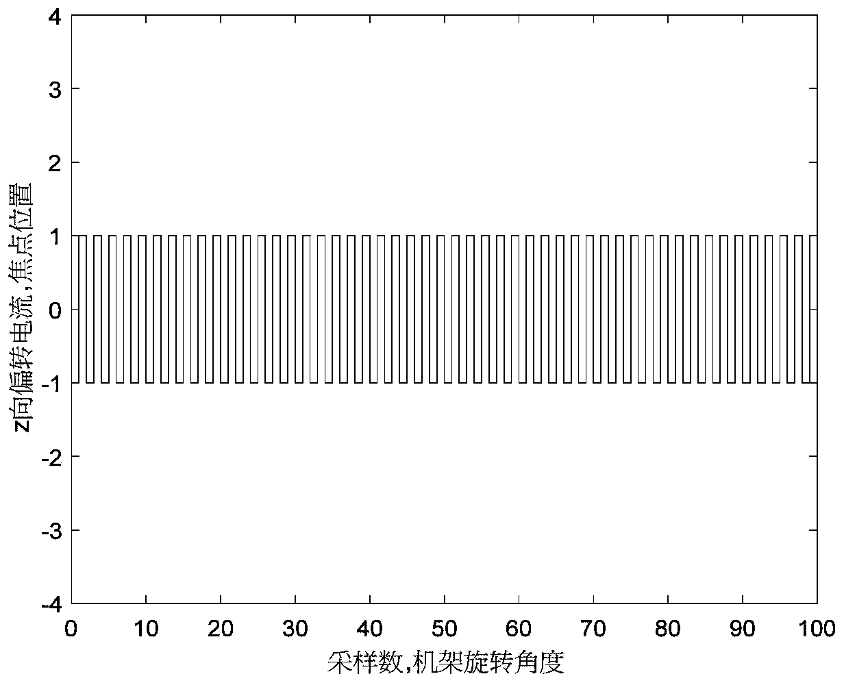
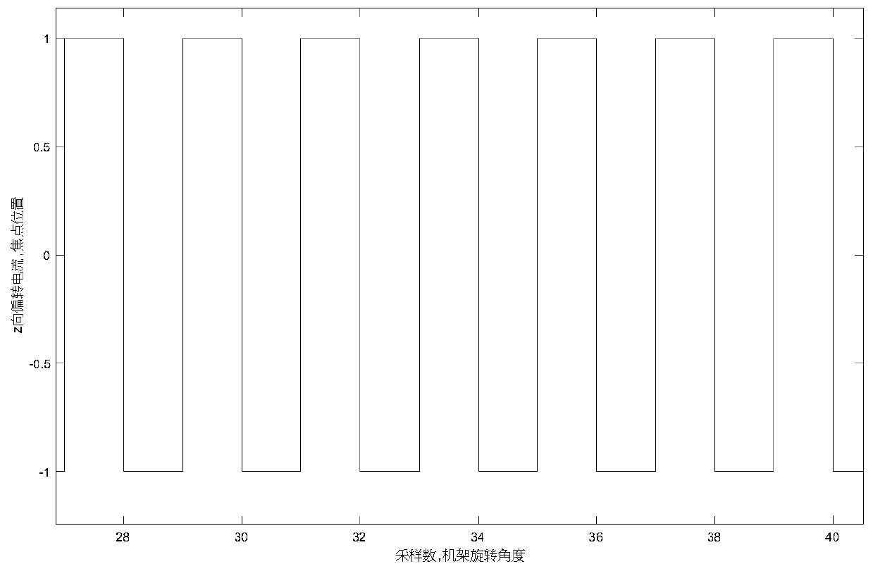
[0041] In the usual Z-direction flying focal point axis-sweep scanning method, when the Z-direction flying focal point is used, two different focal points are used in two adjacent samples. During gantry rotation, odd-numbered samples correspond to one focal point, while even-numbered samples correspond to the other focal point. The control of the focus position in the Z direction is controlled by changing the deflection coil current of the electron beam in the Z direction deflection angle, and its control waveform is as follows figure 2 Shown is a square wave (or a trapezoidal or sine wave can be used because the current rise rate is not enough). image 3 yes figure 2 It can ...


PUM


Abstract

The invention provides a z-direction fly focus scanning mode and an image reconstruction method, and relates to the technical field of medical images, the z-direction fly focus scanning mode comprises Z-direction fly focus sampling, adjustment of positions of two adjacent focuses, rotation of a frame shaft by 180 degrees in an axial scanning mode, Z-direction fly focus control, and linear change slope design. The image reconstruction method comprises the following steps: respectively rearranging data of two focuses to form two parallel beams; carrying out interpolation in the angle direction, so that the scanning data angles of the two fly focuses are the same; performing interpolation in the radial direction, so that the non-equidistant parallel beams of the two focuses are converted into equidistant parallel beams; respectively carrying out filtering operation on the two parallel beams; back projection calculation. According to the Z-direction fly focus axis scanning mode and the image reconstruction method, reconstruction can be carried out at any position in the Z direction to obtain images with completely identical layer thicknesses; meanwhile, the number of Z-direction sampling points is increased through the special axis scanning mode and the reconstruction method, and therefore Z-direction aliasing artifacts are reduced.

Description

technical field [0001] The invention relates to the technical field of medical imaging, in particular to a z-direction femto-focus scanning method and an image reconstruction method. Background technique [0002] The main components of the third-generation CT system include Tube (ball tube), Collimator (beam limiter), and Detector (detector). The X-ray tube emits X-rays, which are limited by a beam limiter to form a cone-shaped beam. The cone-shaped light beam is irradiated on the detector and converted into an electrical signal by the detector, and then converted into digital information by the data acquisition and conversion unit and stored in the image processing system. The image processing system generates images and displays them on the monitor through a series of correction algorithms and image reconstruction algorithms. In terms of cost and technology maturity, mainstream detectors use many detector modules arranged on an arc or polygonal surface to form the entire...

Claims


Application Information

Patent Timeline
Patent Type & Authority Applications(China)
IPC IPC(8): G06T11/00G06T3/40A61B6/00
CPCA61B6/52A61B6/5258G06T3/4007G06T11/003G06T11/008
Inventor 王斌王瑶法黄俊杰陈婷
Owner FMI MEDICAL SYST CO LTD
Learn More