Automatic assembly device for RF line terminal

A technology of automatic assembly and equipment, applied in the assembly/disassembly of contacts, antenna connectors, contact manufacturing, etc., can solve the problem of inability to meet the development trend of high efficiency, high quality and low cost, difficult to choose between processing output and processing cost, no Operation mode automation equipment and other issues, to achieve the effect of intelligent and continuous assembly production, high degree of automation, and labor saving

Pending Publication Date: 2019-09-20
COCENTRA PRECISION TECH (JIANGSU) CO LTD
View PDF0 Cites 1 Cited by
  • Summary
  • Abstract
  • Description
  • Claims
  • Application Information

AI Technical Summary

Problems solved by technology

[0002] The RF wire end is the wire end structure of the radio frequency antenna used in mobile phones, etc. It is generally composed of three parts, namely the plastic sleeve, the terminal and the shell. When the three materials come in, they are all tapes, which need to go through various common processes and actions. Now The plastic sleeve and the terminal are combined into a semi-finished product, and then assembled with the shell to form a finished RF terminal, and its quality inspection is also carried out. Due to the complicated process and cumbersome procedures, but limited by technology, many processes are currently carried out manually. The output of processing depends on the proficiency of employees, and can only rely on the operation of old employees. The speed of new employees under one year is only 1 / 3 of the speed of old employees. In addition to the turnover rate of employees and other reasons, skilled employees need to Long-term support may not be able to stay, and the salaries of old employees are relatively high, making it difficult to choose between processing output and processing cost
Furthermore, manual operation is laborious, high cost and low production capacity
[0003] This manual assembly operation method cannot meet the development trend of high efficiency, high quality and low cost required for mass production
At present, there is no other better operation mode or automatic equipment that can solve the above problems

Method used


Image

  • Automatic assembly device for RF line terminal
  • Automatic assembly device for RF line terminal
  • Automatic assembly device for RF line terminal

Examples


Embodiment

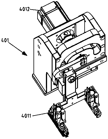
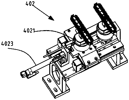
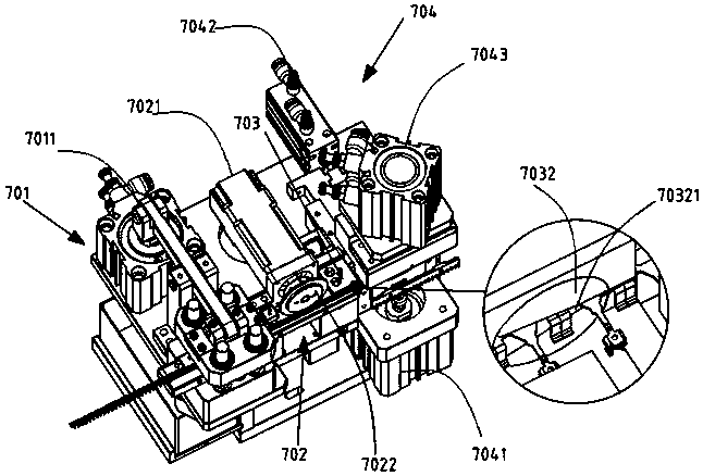
[0050] Embodiment: a kind of RF wire end automatic assembly equipment, such as Figure 1.1 and Figure 1.2 As shown, it includes a machine 10 and a plastic sleeve discharge device 20 provided on the machine, a plastic sleeve feeding and cutting station 30, a plastic sleeve handling and cutting rotary station 40, a main rotary table 50, and a terminal discharging Device 60, terminal cutting and feeding pressing station 70, shell discharging device 80, shell feeding and pressing station 90, semi-finished interpolation station 110, finished product folding belt station 120 and finished product inspection station 130;

[0051] The plastic sleeve feeding and cutting station is located downstream of the plastic sleeve discharging device, and the plastic sleeve handling and cutting rotary station is located downstream of the plastic sleeve feeding and cutting station;

[0052] The terminal cutting, feeding and pressing station is located downstream of the terminal discharging device;...


PUM


Abstract

The present invention discloses an automatic assembly device for a RF line terminal, which comprises a machine, a plastic sleeve discharge device arranged on the machine, a plastic sleeve feeding cutting station, a plastic sleeve conveying cutting rotating station, a main rotating worktable, a terminal discharge device, a terminal cutting feeding press-in station, a shell discharge device, a shell feeding pressing station, a semi-finished product interpolation station, a finished product strip material breaking workstation and a finished product inspection station. The invention adopts a fully automatic operation mode; each mechanism can automatically reset after operation so that a large number of labor can be saved; only a strip material tray need be manually placed in the whole process, so one-worker-multiple-machine can be realized; and the efficiency is improved while the labor cost is reduced.

Description

technical field [0001] The invention belongs to the technical field of automation equipment, in particular to an automatic molding machine. Background technique [0002] The RF wire end is the wire end structure of the radio frequency antenna used in mobile phones, etc. It is generally composed of three parts, namely the plastic sleeve, the terminal and the shell. When the three materials come in, they are all tapes, which need to go through various common processes and actions. Now The plastic sleeve and the terminal are combined into a semi-finished product, and then assembled with the shell to form a finished RF terminal, and its quality inspection is also carried out. Due to the complicated process and cumbersome procedures, but limited by technology, many processes are currently carried out manually. The output of processing depends on the proficiency of employees, and can only rely on the operation of old employees. The speed of new employees under one year is only 1 / 3...

Claims


Application Information

Patent Timeline
Patent Type & Authority Applications(China)
IPC IPC(8): H01R43/16H01R43/18H01R43/20
CPCH01R43/16H01R43/18H01R43/20H01R2201/02
Inventor 蔡喜瑞屈江涛
Owner COCENTRA PRECISION TECH (JIANGSU) CO LTD
Why Eureka
Try Eureka