Supercharge Your Innovation With Domain-Expert AI Agents!

Automatic pre-bending device and bending method for motor rotor iron core

A motor rotor and pre-bending technology, applied in electromechanical devices, electric components, manufacturing motor generators, etc., can solve the problems of large number of broken magnetic steel 19, easy damage to magnetic steel 19, hidden dangers to quality and safety, etc., to achieve crushing The effect of reducing the efficiency, eliminating the occurrence of defective products, and improving the quality of finished products

Active Publication Date: 2020-07-21
东风博泽汽车系统有限公司
View PDF5 Cites 0 Cited by
  • Summary
  • Abstract
  • Description
  • Claims
  • Application Information

AI Technical Summary

Problems solved by technology

The existing motor rotor 15 has the following methods for fixing the magnetic steel 19: the motor rotor 15 is composed of several rotor iron chips 18 stacked in sequence, and each rotor iron chip 18 has the same structure, and the rotor iron chips 18 evenly have a number of insertion and matching grooves. The plug-in fitting grooves of all rotor iron chips 18 of the motor rotor 15 form a plug-in groove, and the magnetic steel 19 is interference-fitted and plugged in the plug-in groove of the motor rotor 15, because the plug-in groove of the magnetic steel 19 and the motor rotor 15 The interference fit between them is plugged in, so that the magnetic steel 19 is easily damaged during the plugging process
This process of fixing the magnetic steel has certain hidden dangers in quality and safety. The number of broken magnetic steel 19 is large, and a second inspection is required to eliminate defective products, which is time-consuming and laborious.

Method used


Image

  • Automatic pre-bending device and bending method for motor rotor iron core
  • Automatic pre-bending device and bending method for motor rotor iron core
  • Automatic pre-bending device and bending method for motor rotor iron core

Examples


Embodiment

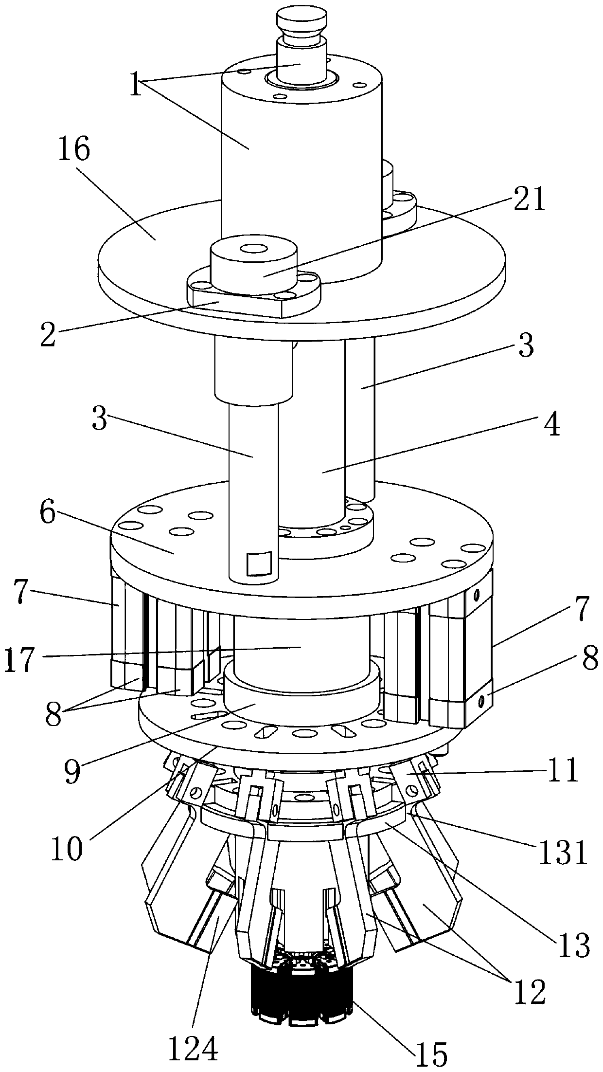
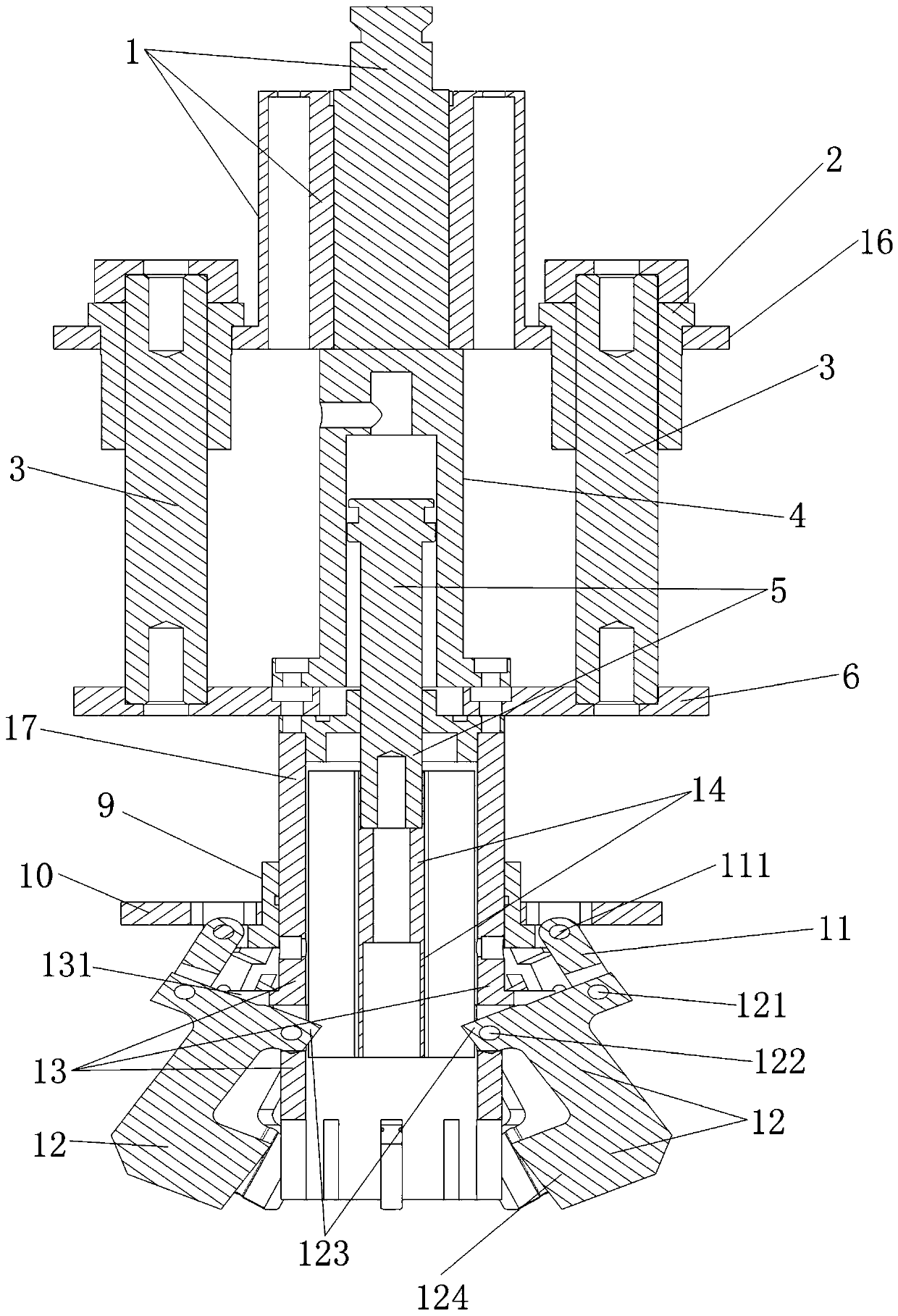
[0034] Such as Figure 1 to Figure 5 As shown, an automatic pre-bending device for a motor rotor core includes a mounting column 1, a top plate 16, a pressing cylinder 4, a clamping cylinder mounting plate 6, a clamping cylinder 7, a push plate 10 and a bending tool holder 13, A mounting column 1 is fixedly installed on the top of the top plate 16, and a down-pressing cylinder 4 is installed between the center of the top plate 16 and the center of the clamping cylinder mounting plate 6. The down-pressing cylinder 4 has a down-pressing piston rod 5, and the down-pressing cylinder 4 drives the down-pressing piston rod 5 telescopic movement. The bottom of the clamping cylinder mounting plate 6 is fixedly installed with a pressure head cylinder 17, and the lower end of the pressing piston rod 5 penetrates the center of the clamping cylinder mounting plate 6 and is placed in the pressure head cylinder 17 to lift and slide. The external sliding sleeve of the pressure head cylinder 1...


PUM


Abstract

The invention discloses an automatic pre-bending device and method for a motor rotor core. The automatic pre-bending device comprises an installation column, a top plate, clamping cylinders installation plate, a clamping cylinder and a bending cutter holder, wherein the top plate and the clamping cylinder installation plate are equipped with a downward pressing cylinder therebetween, the bottom of the clamping cylinder installation plate is fixedly equipped with a pressing head cylinder, the external part of the pressing head cylinder is slidably sleeved with a push plate, the lower end of the pressing head cylinder is fixedly equipped with the bending cutter holder, the push plate is equipped with a plurality of connecting rods in a movable hinged manner, and the bending cutter holder is equipped with a plurality of bending cutters; and the lower end part of a downward pressing piston rod is fixedly equipped with a rotor pressing head located inside the pressing head cylinder, the bottom of the clamping cylinder installation plate is fixed with a plurality of clamping cylinders, and the lower end part of a telescopic rod of each clamping cylinder is connected and fixed with the top surface of the push plate. According to the invention, spring tabs of a motor rotor are pre-bent, and then magnetic steel is installed in a matched manner, thereby being capable of stably fixing the magnetic steel, enabling the magnetic steel breakage rate to be reduced or even disappear, improving the qualified rate of products, and improving the quality of finished motor products.

Description

technical field [0001] The invention relates to the technical field of motor component manufacturing, in particular to an automatic pre-bending device and a bending method for a motor rotor iron core. Background technique [0002] The motor has a wide range of uses. The motor rotor 15 is a very important part of the motor. In the manufacturing process of motor parts, some types of motor rotors 15 need to be installed with magnetic steel 19 during the manufacturing process. The motor rotor 15 is often made of interference The magnetic steel 19 is fixed by cooperating with the plugging mode. The existing motor rotor 15 has the following methods for fixing the magnetic steel 19: the motor rotor 15 is composed of several rotor iron chips 18 stacked in sequence, and each rotor iron chip 18 has the same structure, and the rotor iron chips 18 evenly have a number of insertion and matching grooves. The plug-in fitting grooves of all rotor iron chips 18 of the motor rotor 15 form a ...

Claims


Application Information

Patent Timeline
Patent Type & Authority Patents(China)
IPC IPC(8): H02K15/03
CPCH02K15/03
Inventor 阮洋郑传汉罗军
Owner 东风博泽汽车系统有限公司
Features
  • R&D
  • Intellectual Property
  • Life Sciences
  • Materials
  • Tech Scout
  • Unparalleled Data Quality
  • Higher Quality Content
  • 60% Fewer Hallucinations
Learn More