Eureka AIR delivers breakthrough ideas for toughest innovation challenges, trusted by R&D personnel around the world.

Combination structure of evaporation-boiling capillary core coupled with liquid replenishment capillary core

A combined structure and capillary core technology, which is applied in the construction of electrical equipment components, cooling/ventilation/heating transformation, lighting and heating equipment, etc., can solve the problems of unclear transformation mechanism, improve the liquid capillary pumping capacity, improve Phase-change heat capacity to achieve the effect of heat dissipation

Active Publication Date: 2020-04-28
XI AN JIAOTONG UNIV
View PDF7 Cites 0 Cited by
  • Summary
  • Abstract
  • Description
  • Claims
  • Application Information

AI Technical Summary

Problems solved by technology

However, the transition mechanism between thin film evaporation and nucleate boiling is still unclear. How to extend the heat dissipation capability of ultra-high heat flux in a small area (millimeter level) to a larger area, and at the same time delay the dry burning of the center or local hot spot of the heating surface problems and challenges

Method used

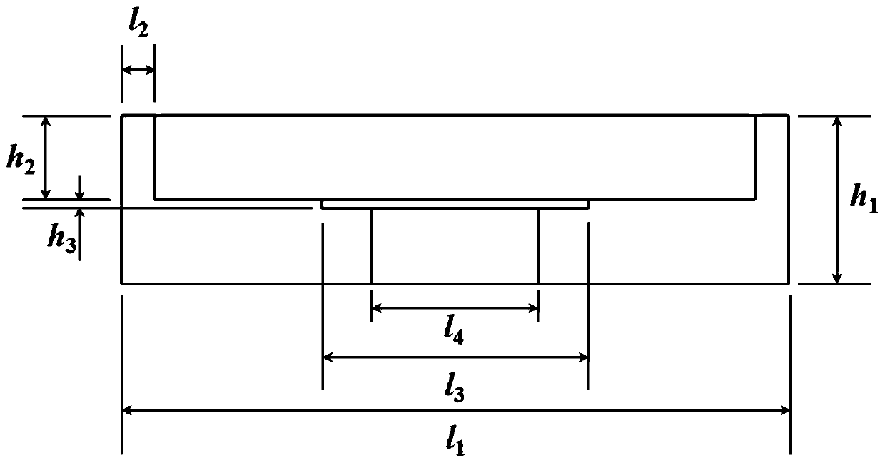

Image

  • Combination structure of evaporation-boiling capillary core coupled with liquid replenishment capillary core
  • Combination structure of evaporation-boiling capillary core coupled with liquid replenishment capillary core
  • Combination structure of evaporation-boiling capillary core coupled with liquid replenishment capillary core

Examples


Embodiment Construction

[0035] Below in conjunction with accompanying drawing, the present invention is described in further detail:

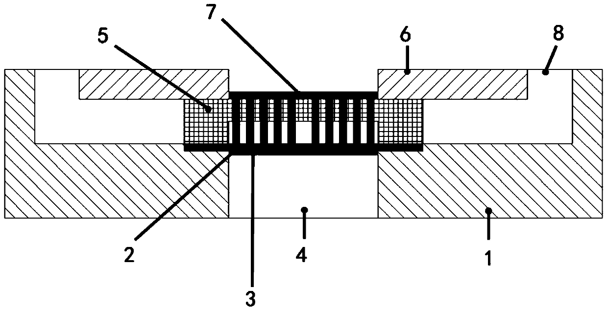
[0036] A combination structure of evaporation-boiling capillary core coupled with liquid replenishment capillary core, such as figure 1 As shown, it includes the lower substrate 1 of the rehydration channel, the evaporation-boiling capillary core 2, the ITO heating film 3, the heat insulating material 4, the rehydration capillary wick 5, the upper substrate 6 of the rehydration channel, the nano-evaporation film 7, the rehydration channel 8, and under the rehydration channel The evaporation-boiling capillary core 2 is arranged on the substrate 1, the ITO heating film 3 is sputtered at the bottom of the evaporation-boiling capillary core 2, the evaporation-boiling capillary core 2 is heated by the ITO heating film 3, and the heat insulating material 4 is arranged at the bottom of the ITO heating film 3 , to prevent the loss of heat; at the same time, the liquid repleni...


PUM

PropertyMeasurementUnit
heightaaaaaaaaaa
sizeaaaaaaaaaa
widthaaaaaaaaaa

Abstract

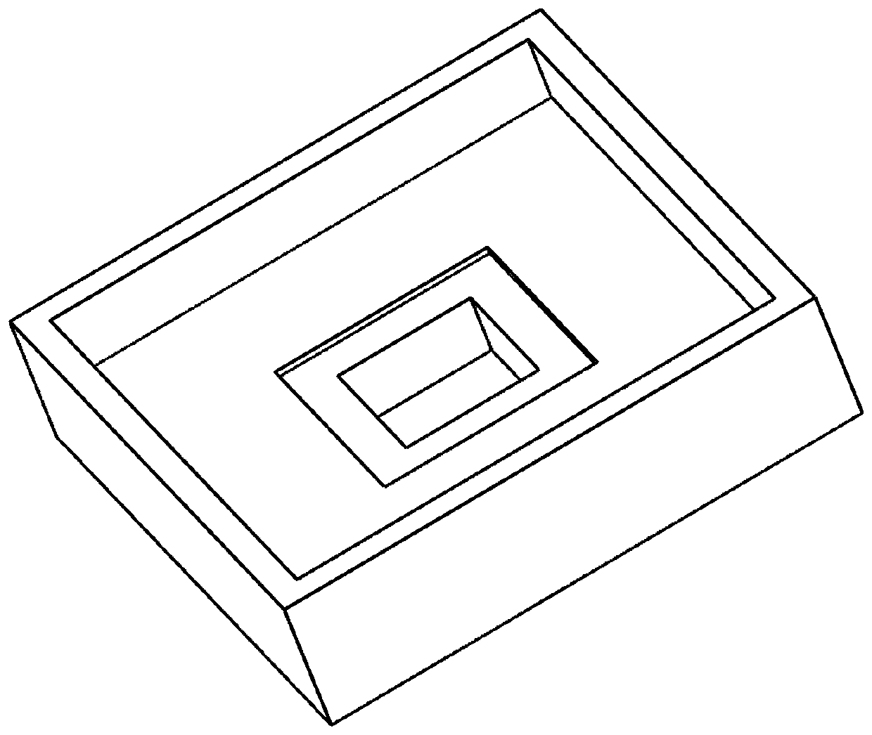
The invention discloses an evaporation-boiling capillary core and liquid-supplementing capillary core coupled combined structure. The combined structure comprises a liquid-supplementing channel lower substrate; a first groove is formed in the middle of the liquid-supplementing channel lower substrate; a second groove is formed in the middle of the first groove; a groove channel is formed in the middle of the second groove; a substrate of an evaporation-boiling capillary core is arranged in the second groove; an ITO heating film is sputtered at the bottom of the evaporation-boiling capillary core; a heat insulation material is arranged at the bottom of the ITO heating film; the heat insulation material is arranged in the groove channel; a liquid-supplementing capillary core is arranged in the first groove; the liquid-supplementing capillary core is arranged at the periphery of the evaporation-boiling capillary core; a liquid-supplementing channel upper substrate is arranged on the upper side of the liquid-supplementing capillary core; a through groove is formed in the middle of the liquid-supplementing channel upper substrate; a nano evaporation film is arranged in the through groove; the nano evaporation film covers the upper side of the evaporation-boiling capillary core; a liquid-supplementing channel is formed between the liquid-supplementing channel lower substrate and the liquid-supplementing channel upper substrate; and the liquid-supplementing channel communicates with a channel of the liquid-supplementing capillary core.

Description

technical field [0001] The invention relates to the field of thin-film phase change heat transfer in tiny spaces in micro-nano heat transfer, in particular to an evaporation-boiling capillary core coupled liquid replenishment capillary core combined structure. Background technique [0002] With the rapid development of various electronic devices such as microprocessors, solar cells, laser diodes, and radio frequency power amplifiers, electronic devices are rapidly showing two trends: miniaturization and integration. Boiling heat transfer is a violent vaporization process that converts the working medium from liquid to vapor through the generation, growth and detachment of a large number of bubbles. Compared with traditional air cooling and convective heat transfer, the heat transfer coefficient has an order of magnitude difference , so it is a very effective way to dissipate heat. The basic research on the mechanism of phase transition shows that the main mechanism of nucle...

Claims


Application Information

Patent Timeline
Patent Type & Authority Patents(China)
IPC IPC(8): H05K7/20F28F13/18F28D15/04
CPCF28D15/046F28F13/18H05K7/20336
Inventor 张永海李瑞华徐鹏卓刘斌魏进家
Owner XI AN JIAOTONG UNIV
Why Eureka
Eureka Blog
Learn More