
A microwave resonator, a microwave filter and a microwave multiplexer

A resonator and microwave coupler technology, applied in resonators, waveguide devices, circuits, etc., can solve the problems of large resonators, achieve high Q value, reduce size, and make simple effects

Inactive Publication Date: 2019-09-20
ISOTEK MICROWAVE
View PDF10 Cites 4 Cited by
  • Summary
  • Abstract
  • Description
  • Claims
  • Application Information

AI Technical Summary

Problems solved by technology

As a result, the resonator is larger

Method used


Image

  • A microwave resonator, a microwave filter and a microwave multiplexer
  • A microwave resonator, a microwave filter and a microwave multiplexer
  • A microwave resonator, a microwave filter and a microwave multiplexer

Examples


Embodiment Construction

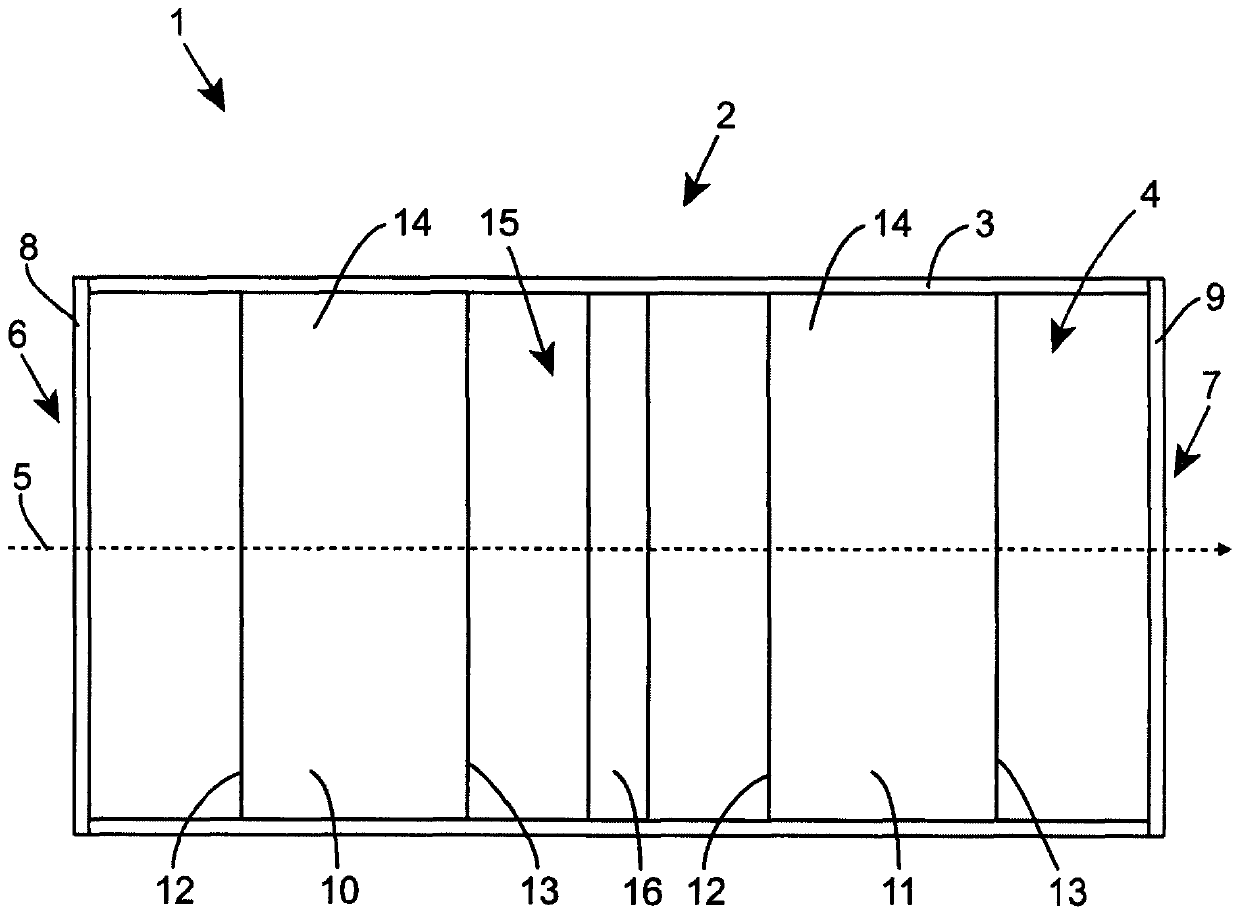
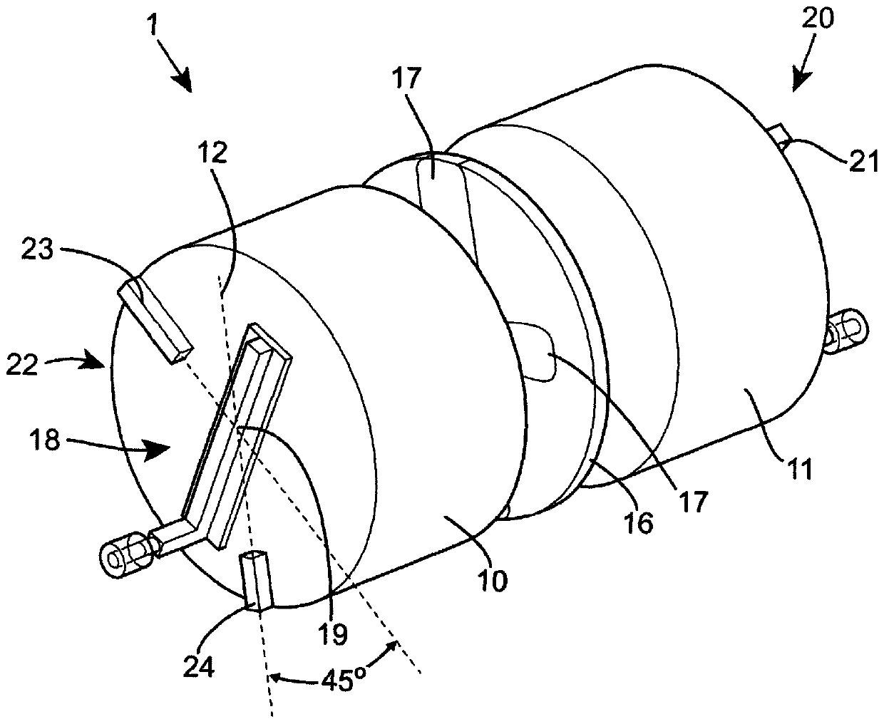
[0081] figure 1 An embodiment of a microwave resonator 1 according to the invention is shown in vertical section in . The microwave resonator 1 of this embodiment is a quadrupole microwave resonator 1 .

[0082] The microwave resonator 1 comprises a hollow tube 2 . The hollow tube 2 comprises a conductive tube wall 3 defining a tube hole 4 . The tube bore 4 extends along the length axis 5 from the first end 6 of the tube 2 to the second end 7 of the tube 2 . The tube bore 4 of this embodiment of the invention is circular and perpendicular to the length axis 5 .

[0083] A first electrically conductive closing plate 8 closes the first end 6 of the tube 2 . A second electrically conductive closing plate 9 closes the second end 7 of the tube 2 .

[0084] A first dielectric resonant disc 10 and a second dielectric resonant disc 11 are arranged in the tube hole 4 . Each disk 10 , 11 includes a first end surface 12 and a second end surface 13 and a side wall 14 extending betwe...


PUM


Abstract

A microwave resonator comprising a hollow tube comprising f an electrically conductive tube wall which defines a tube bore, the tube extending along a length axis from a first end to a second end; a first electrically conductive closing plate closing the first end of the tube; a second electrically conductive closing plate closing the second end of the tube; a plurality of dielectric resonant pucks, each puck comprising first and second end faces and a side wall extending therebetween, each puck being dimensioned such that its dominant mode is a doubly degenerate mode; the pucks being arranged within the tube bore spaced apart from each other and the closing plates, each puck being arranged with its end faces normal to the length axis and centered on the length axis and its side wall abutting the tube wall such that there is no air gap between the puck and tube wall which extends from one end face to the other of the puck, the puck adjacent to the first closing plate being termed the input puck; each puck being separated from the adjacent puck in the tube bore by a coupling gap, each coupling gap having ah electrically conductive iris plate arranged therein, each iris plate being arranged normal to the length axis, each iris plate comprising at least one coupling slot extending therethrough; an input microwave coupler adapted to receive a microwave signal and provide it to the input puck; each puck comprising a symmetry breaking structure for modifying the frequency of one of the degenerate modes relative to the other and the coupling between the two modes.

Description

technical field [0001] The invention relates to a microwave resonator. More particularly but not exclusively, the present invention relates to a microwave resonator comprising: a hollow tube defined by conductive tube walls, the tube closed at both ends by closing plates; and a plurality of a plurality of spaced apart dielectric resonant disks arranged in the tube, each disk sized to resonate in a doubly degenerate dominant mode, each disk comprising a symmetric A symmetry-breaking structure that is used to modify the frequency of one degenerate mode relative to another and the coupling between the two modes. The invention also relates to a microwave filter comprising a plurality of such microwave resonators. The invention also relates to a microwave multiplexer comprising a plurality of such resonators. Background technique [0002] Microwave resonators are common components in microwave devices such as microwave filters and multiplexers. Such microwave resonators usual...

Claims


Application Information

Patent Timeline
Patent Type & Authority Applications(China)
IPC IPC(8): H01P1/208
CPCH01P1/2086H01P7/105H01P5/02H01P7/06
Inventor 约翰·戴维·罗兹戴维·伊贝森瓦内萨·沃克克利斯托弗·伊恩·莫布斯
Owner ISOTEK MICROWAVE
Learn More