Desulfurization slurry spraying device

A technology of spraying device and desulfurization slurry, which is applied in the direction of liquid spraying device, spraying device, liquid separation agent, etc., can solve the problems such as small overlap of desulfurization tower edges, non-crossing spray layers, and short circuit of flue gas, etc., to achieve improved Operational stability and reliability, solve the phenomenon of flue gas escape along the wall, improve the effect of desulfurization rate and dust removal rate

Pending Publication Date: 2019-09-24
浙江菲达环保科技股份有限公司 +2
View PDF0 Cites 2 Cited by
  • Summary
  • Abstract
  • Description
  • Claims
  • Application Information

AI Technical Summary

Problems solved by technology

[0005] 1. Since the nozzles of the existing spraying device are evenly arranged on the entire cross-section, after the slurry is sprayed through the nozzles, the slurry mist crowns overlap each other, the central area has a large overlap, and the edge of the desulfurization tower has a small overlap, resulting in a large amount of flue gas along the wall escape, the removal rate of sulfur dioxide and dust is greatly reduced;
[0006] 2. In order to ensure a certain spray coverage, the distance between the nozzles has certain requirements, and the atomized slurry often causes erosion and wear on the support beam and the larger diameter of the main pipe;
[0007] 3. When individual nozzles are blocked, a short circuit of flue gas will be formed, SO 2 And dust is easy to exceed the standard discharge;
[0008] 4. The spray layers do not cross each other, or the cross angle is not suitable, so that the weak areas between the upper and lower spray layers cannot offset each other, especially along the area near the tower

Method used


Image

  • Desulfurization slurry spraying device
  • Desulfurization slurry spraying device
  • Desulfurization slurry spraying device

Examples


Embodiment Construction

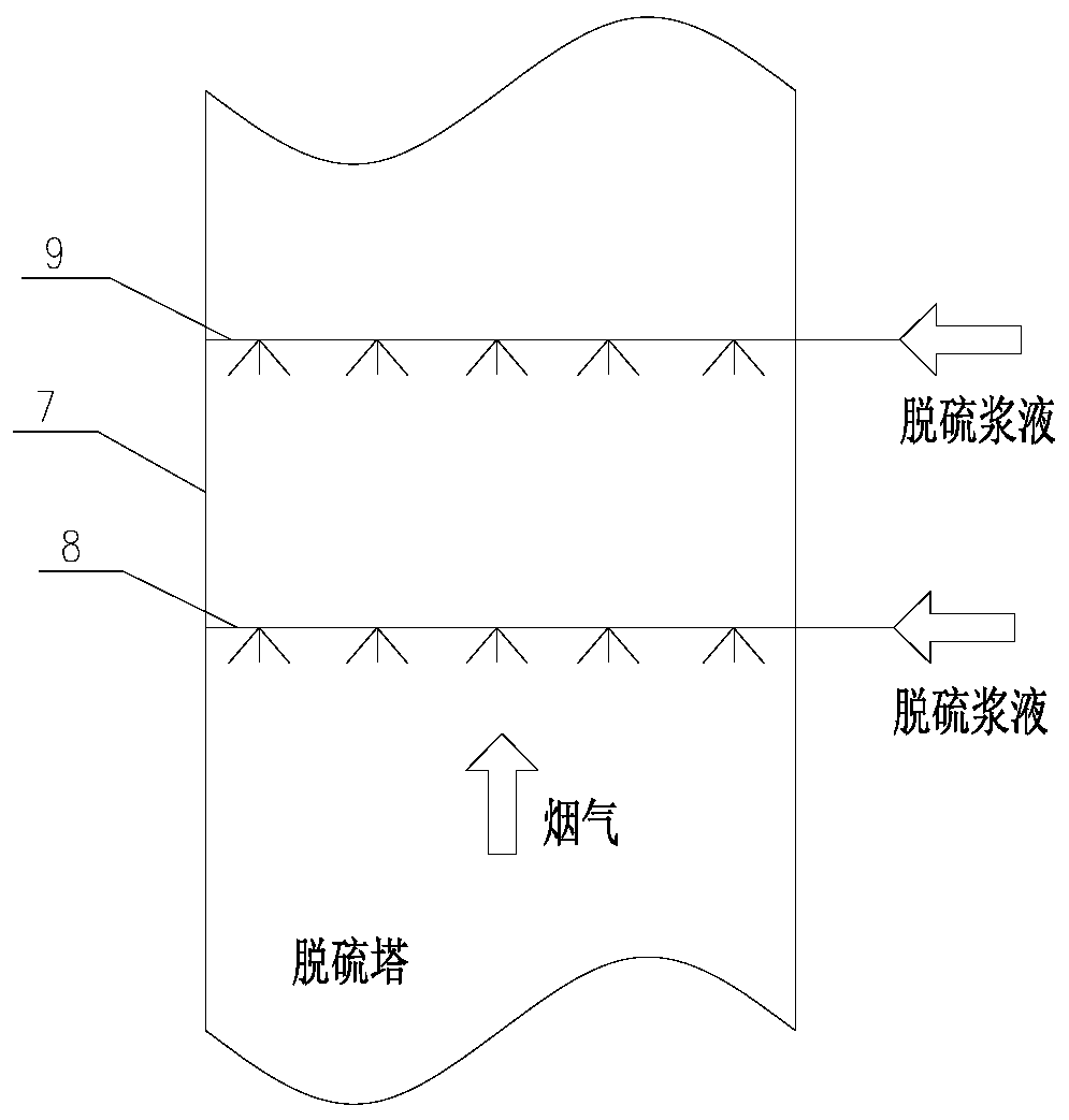
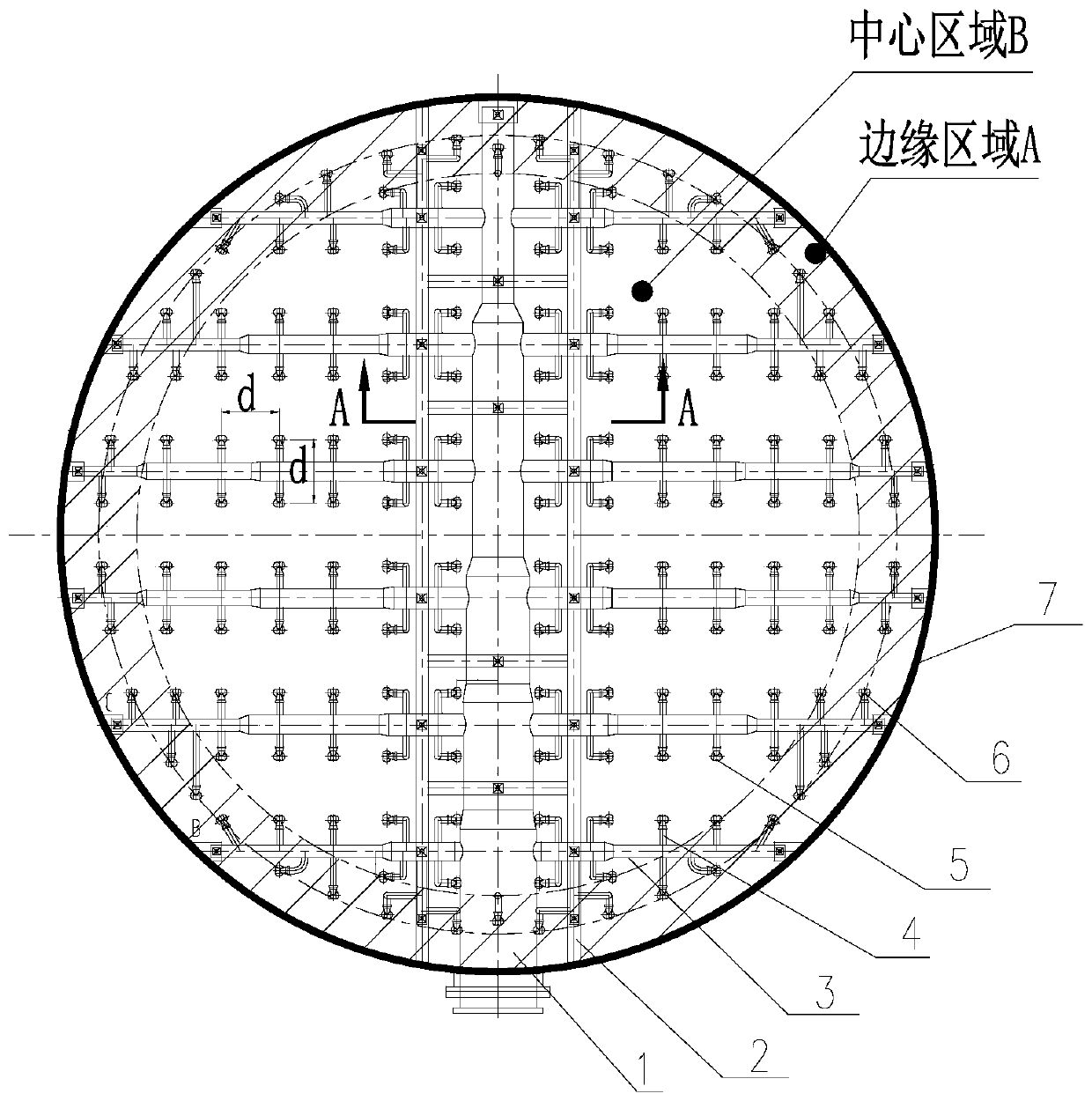
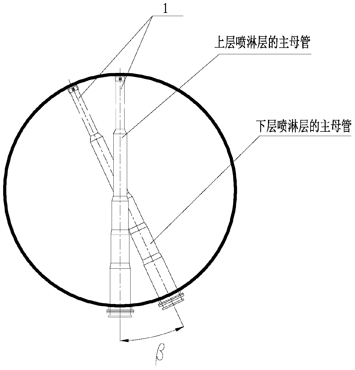
[0025] refer to Figure 1 to Figure 5 A desulfurization slurry spray device of the present invention is composed of more than two spray layers, the spray layers are sequentially arranged in the desulfurization tower from top to bottom, and the spray layers include main main pipe 1, support beam 2, secondary main pipe Pipe 3, branch pipe 4, first nozzle 5 and second nozzle 6, the main main pipe 1 is supported by a support beam 2, and the two ends of the support beam 2 are fixed on the tower wall 7 of the desulfurization tower. Both sides of the pipe 1 are connected with several secondary main pipes 3, and both sides of the secondary main pipe 3 are connected with several branch pipes 4, and the branch pipes 4 are not terminated with nozzles, and the nozzles include the first nozzle 5 or the second nozzle 6 , the two adjacent spray layers are composed of an upper spray layer 9 and a lower spray layer 8, the top view projection of the main master pipe 1 of the lower spray layer 8...


PUM


Abstract

The invention provides a desulfurization slurry spraying device. The desulfurization slurry spraying device is composed of two or more layers of spraying layers, wherein the spraying layers are sequentially distributed in a desulfurization tower from top to bottom, the spraying layers comprise primary mother tubes, supporting beams, secondary mother tubes, branches, first nozzles and second nozzles, the primary mother tubes are supported by the supporting beams, two ends of each supporting beam are fixed to a tower wall of the desulfurization tower, the corresponding secondary mother tubes are connected with two sides of each primary mother tube, the corresponding branches are connected with two sides of each secondary mother tube, the tail ends of the branches are connected with nozzles, the nozzles comprise the first nozzles or the second nozzles, each two adjacent spraying layers are composed of an upper-layer spraying layer and a lower-layer spraying layer, and an included angle beta of downward projections of the corresponding primary mother tube of each lower-layer spraying layer and the corresponding primary mother tube of the corresponding upper-layer spraying layer exists. By means of the spraying device, the phenomenon of escape of smoke along a wall can be solved basically, the desulfurization rate and the dust removal rate are improved, a liquid-gas ratio can be reduced appropriately, and more strict requirements of environmental protection can be met.

Description

【Technical field】 [0001] The invention relates to the technical field of spraying devices, in particular to a desulfurization slurry spraying device. 【Background technique】 [0002] The spray device is one of the core equipment of the wet desulfurization spray tower, which has a direct impact on the desulfurization efficiency and dust removal rate. The spray device is generally composed of a support, a main pipe, a branch pipe and a nozzle. The desulfurization slurry enters the spray device through the pump, and the slurry is distributed to the nozzle through the main pipe and the branch pipe. Contact to achieve the purpose of removing sulfur dioxide and dust. [0003] The existing conventional spraying device is composed of 2 to 5 layers of spraying layers, which are arranged up and down in the desulfurization tower. Each layer of spraying layer is equipped with 1 to 2 main pipes, and several branch pipes are arranged on both sides of each main pipe. Side nozzle. General...

Claims


Application Information

Patent Timeline
Patent Type & Authority Applications(China)
IPC IPC(8): B01D53/80B01D53/50B01D47/06B05B9/00
CPCB01D47/06B01D53/50B01D53/80B01D2258/0283B05B9/00
Inventor 张永赵书盈史新峰王少权李军刘中显王新龙刘峰李建男马红瑞蔡铁城何红儿
Owner 浙江菲达环保科技股份有限公司
Why Eureka
Try Eureka