
Novel oil pipe head and sleeve head machining device

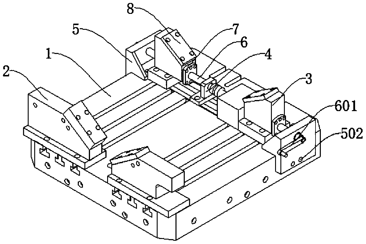
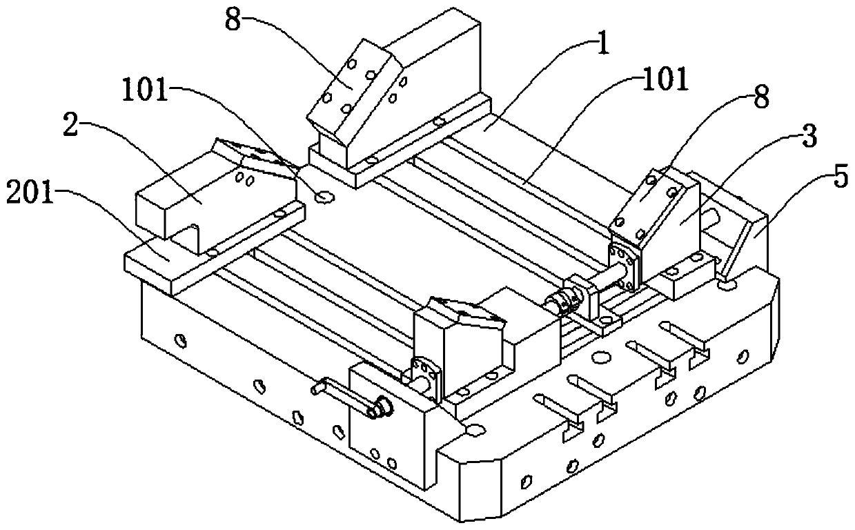
A processing device and oil pipe head technology, which is applied in positioning devices, metal processing equipment, metal processing machinery parts, etc., can solve the problems of equipment processing, shape accuracy cannot be guaranteed, and complex calibration, etc., to release pressure and reduce management costs and repair and maintenance costs, and the effect of improving machining accuracy

Pending Publication Date: 2019-09-24
SUZHOU UNIQUE FLOW CONTROL TECH CO LTD
View PDF0 Cites 3 Cited by
  • Summary
  • Abstract
  • Description
  • Claims
  • Application Information

AI Technical Summary

Problems solved by technology

[0004] But in the prior art, there are the following problems when processing the oil pipe head and the casing head. The equipment cannot be processed, and even if the shape accuracy is processed, it cannot be guaranteed; 2. Due to the inclined surface and various angle oil holes in the casing head processing, it needs to be processed in the horizontal processing. Two or more V-shaped blocks are required, and there are many tooling details. , the versatility is not strong; 3. Due to the inclined surface and various angle oil holes in the processing of the oil pipe head, and the drop between the two flanges, two V-shaped blocks of different heights are required. There are many tooling details, and the versatility is not strong. Complex, so the existing tubing head and casing head processing technology does not have the ability to quickly debug and produce, so it needs to be improved

Method used


Image

  • Novel oil pipe head and sleeve head machining device
  • Novel oil pipe head and sleeve head machining device
  • Novel oil pipe head and sleeve head machining device

Examples


Embodiment Construction

[0027] The following will clearly and completely describe the technical solutions in the embodiments of the present invention with reference to the accompanying drawings in the embodiments of the present invention. Obviously, the described embodiments are only some, not all, embodiments of the present invention.

[0028] In describing the present invention, it should be understood that the terms "upper", "lower", "front", "rear", "left", "right", "top", "bottom", "inner", " The orientation or positional relationship indicated by "outside", etc. is based on the orientation or positional relationship shown in the drawings, and is only for the convenience of describing the present invention and simplifying the description, rather than indicating or implying that the referred device or element must have a specific orientation, so as to Specific orientation configurations and operations, therefore, are not to be construed as limitations on the invention.

[0029] refer to Figure ...


PUM


Abstract

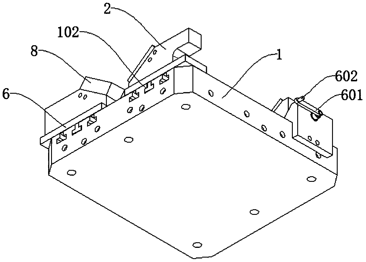
The invention discloses a novel oil pipe head and sleeve head machining device, and belongs to the technical field of oil pipe head manufacturing clamps. The novel oil pipe head and sleeve head machining device comprises a fixing bottom plate, wherein a first T-shaped groove and a second T-shaped groove are formed in the top wall of the fixing bottom plate, a first V-shaped sliding block is slidably connected in the first T-shaped groove, a second V-shaped sliding block and a bearing block are slidably connected in the second T-shaped groove, the fixing bottom plate is further connected with an axis stop seat, the axis stop seat is connected with a screw rod, the screw rod penetrates through the second V-shaped sliding block and is connected to the inner wall of the axis blocking seat, and the screw rod is matched with the bearing seat. The novel oil pipe head and sleeve head machining device reduces the management cost and the maintenance cost of the machining device, improves the machining precision and the core competitiveness of an enterprise, is simple in manufacturing structure and assembly, convenient to use and applicable to various working environments, and greatly improves the machining efficiency.

Description

technical field [0001] The invention relates to the technical field of oil pipe head manufacturing jigs, in particular to a novel oil pipe head and casing head processing device. Background technique [0002] The tubing head is a device component that connects the uppermost casing head and the oil (gas) tree to hang the tubing and seal the annular space between the tubing and the casing; the tubing head is located on the casing head, including the casing spool and the tubing hanger , its function is to suspend the tubing, downhole tools, and seal the annular space of the oil casing in the well; the casing head is generally made of 35 or 42 chrome-molybdenum high-quality alloy structural steel, and a casing hanger is also set in the casing head for Suspend the casing string of corresponding specification, and seal the annular gap, install the blowout preventer group on it, and install the Christmas tree on the casing head after the oil well is completed. [0003] In the well...

Claims


Application Information

Patent Timeline
Patent Type & Authority Applications(China)
IPC IPC(8): B23Q1/25B23Q3/06
CPCB23Q1/25B23Q3/06
Inventor 吴建勇蒯东升朱斌斌
Owner SUZHOU UNIQUE FLOW CONTROL TECH CO LTD
Learn More