A fixture for clamping shaft-type workpieces for CNC milling machines

A CNC milling machine, shaft type technology, applied in the direction of manufacturing tools, metal processing mechanical parts, clamping and other directions, can solve the problems of affecting processing accuracy, axial shaking of shaft type workpieces, etc., to improve processing accuracy, save air, and improve clamping holding effect

Active Publication Date: 2021-04-13
湖南恒鑫银机械科技有限公司
View PDF6 Cites 0 Cited by
  • Summary
  • Abstract
  • Description
  • Claims
  • Application Information

AI Technical Summary

Problems solved by technology

[0003] In order to overcome the disadvantages that the existing fixtures used for CNC milling machines usually only clamp and fix the axial workpiece radially, which may easily cause axial shaking of the axial workpiece and seriously affect the machining accuracy, the technical problem of the present invention is to provide a A fixture for CNC milling machine clamping axial workpieces capable of preventing axial shaking and improving machining accuracy

Method used


Image

  • A fixture for clamping shaft-type workpieces for CNC milling machines
  • A fixture for clamping shaft-type workpieces for CNC milling machines
  • A fixture for clamping shaft-type workpieces for CNC milling machines

Examples


Embodiment 1

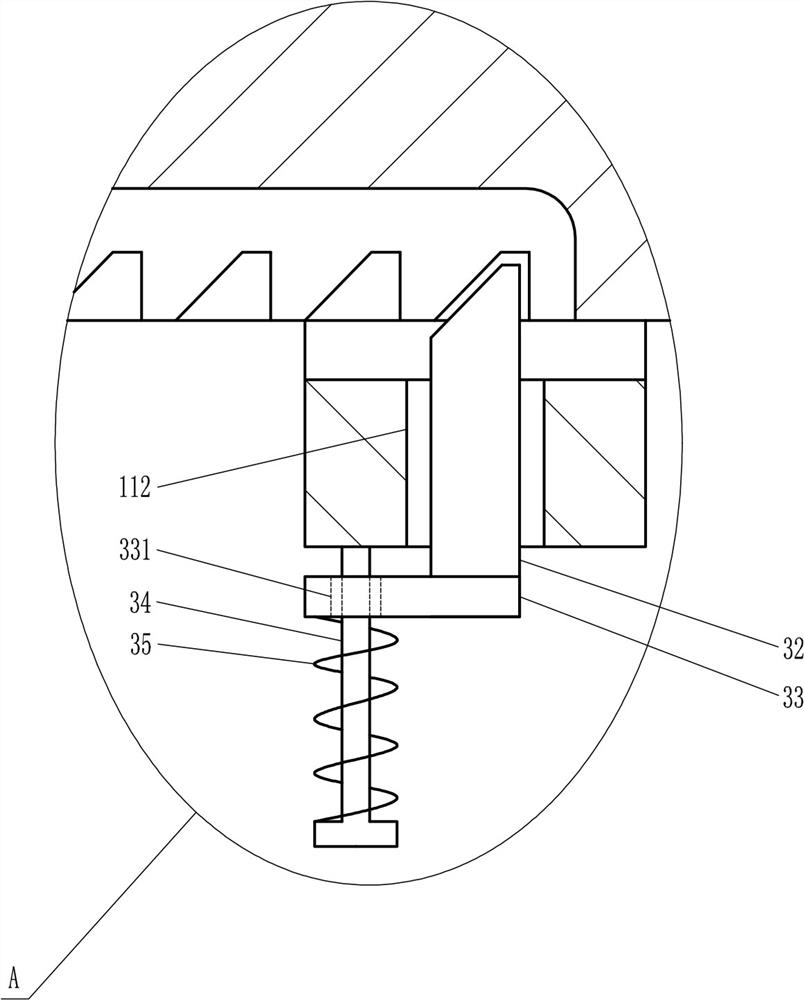
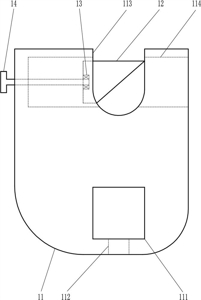
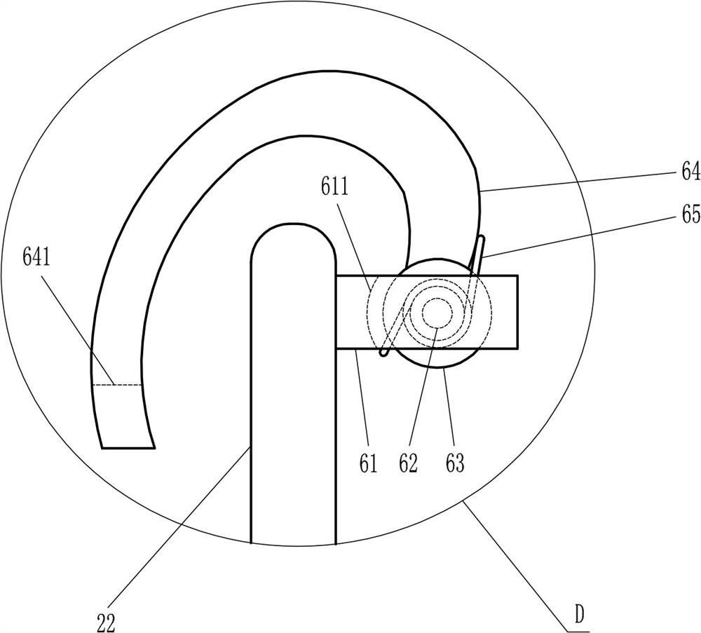
[0023] A fixture for a CNC milling machine to clamp a shaft-type workpiece, such as Figure 1-7 As shown, it includes a base 1, a large bolt 2, a large bracket 3, a rectangular guide rod 4, a large fixed plate 5, an arc-shaped guide plate 6, a ball 7, a small bracket 8, a large screw rod 9, a large tension spring 10, the first Large supporting plate 11, left wedge-shaped clamping plate 12, first bearing 13, first long screw rod 14, first connecting plate 15, first baffle plate 16, second large supporting plate 17, right wedge-shaped clamping plate 18, second bearing 19. The second long screw rod 20, the second connecting plate 21 and the second baffle plate 22. The base 1 has a large through hole 101 that penetrates up and down. The large bolt 2 is located in the large through hole 101 in a sliding manner. The top of the base 1 is connected with a large Support 3, the upper end of large support 3 is hingedly connected with the bottom of rectangular guide bar 4, and the right s...

Embodiment 2

[0025] A fixture for a CNC milling machine to clamp a shaft-type workpiece, such as Figure 1-7 As shown, it includes a base 1, a large bolt 2, a large bracket 3, a rectangular guide rod 4, a large fixed plate 5, an arc-shaped guide plate 6, a ball 7, a small bracket 8, a large screw rod 9, a large tension spring 10, the first Large supporting plate 11, left wedge-shaped clamping plate 12, first bearing 13, first long screw rod 14, first connecting plate 15, first baffle plate 16, second large supporting plate 17, right wedge-shaped clamping plate 18, second bearing 19. The second long screw rod 20, the second connecting plate 21 and the second baffle plate 22. The base 1 has a large through hole 101 that penetrates up and down. The large bolt 2 is located in the large through hole 101 in a sliding manner. The top of the base 1 is connected with a large Support 3, the upper end of large support 3 is hingedly connected with the bottom of rectangular guide bar 4, and the right s...

Embodiment 3

[0028] A fixture for a CNC milling machine to clamp a shaft-type workpiece, such as Figure 1-7As shown, it includes a base 1, a large bolt 2, a large bracket 3, a rectangular guide rod 4, a large fixed plate 5, an arc-shaped guide plate 6, a ball 7, a small bracket 8, a large screw rod 9, a large tension spring 10, the first Large supporting plate 11, left wedge-shaped clamping plate 12, first bearing 13, first long screw rod 14, first connecting plate 15, first baffle plate 16, second large supporting plate 17, right wedge-shaped clamping plate 18, second bearing 19. The second long screw rod 20, the second connecting plate 21 and the second baffle plate 22. The base 1 has a large through hole 101 that penetrates up and down. The large bolt 2 is located in the large through hole 101 in a sliding manner. The top of the base 1 is connected with a large Support 3, the upper end of large support 3 is hingedly connected with the bottom of rectangular guide bar 4, and the right si...


PUM


Abstract

The invention relates to a fixture for a numerically controlled milling machine, in particular to a fixture for a numerically controlled milling machine to clamp a shaft-type workpiece. The technical problem of the present invention is to provide a jig used for a CNC milling machine to clamp a shaft-type workpiece, which can prevent axial shaking and improve machining accuracy. A fixture for clamping shaft-type workpieces for CNC milling machines, including a base, a large bolt, a large bracket, a rectangular guide rod, a large fixed plate, an arc guide plate, a sphere, etc.; The bolt slides in the large through hole, and the top of the base is connected with a large bracket. The fixture provided by the invention for clamping a shaft-type workpiece by a numerical control milling machine can double-clamp and fix the shaft-type workpiece in the radial direction and the axial direction, and the clamping effect is good, thereby preventing the shaft-type workpiece from shaking in the axial direction. It is beneficial to improve the machining accuracy, and it can also tilt the shaft-type workpiece, which is convenient for complex processing of the shaft-type workpiece, and is beneficial to the production and development of the enterprise.

Description

technical field [0001] The invention relates to a fixture for a numerically controlled milling machine, in particular to a fixture for a numerically controlled milling machine to clamp a shaft-type workpiece. Background technique [0002] CNC milling machine, also known as CNC, is an automatic processing equipment developed on the basis of general milling machines. The processing technology of the two is basically the same, and the structure is also somewhat similar. CNC milling machines are divided into two categories: without tool magazine and with tool magazine. Among them, the CNC milling machine with a tool magazine is also called a machining center. After the workpiece is fixed by the fixture, the workpiece can be processed by the CNC milling machine. The existing fixtures for the CNC milling machine usually only perform radial machining on the shaft workpiece. Clamping and fixing can easily lead to axial shaking of the shaft-type workpiece, which seriously affects the...

Claims


Application Information

Patent Timeline
Patent Type & Authority Patents(China)
IPC IPC(8): B23Q3/06
CPCB23Q3/062
Inventor 李琴
Owner 湖南恒鑫银机械科技有限公司
Why Eureka
Try Eureka