Three-degree-of-freedom spherical wrist based on hydraulic direct drive without singular configuration

A degree of freedom and hydraulic technology, applied in the field of robotics, can solve problems such as poor dynamic response characteristics of joints, low load/self-weight ratio, high manufacturing/maintenance costs, etc., and achieve easy wrist posture control, high load/self-weight ratio, and kinematic characteristics simple effect

Active Publication Date: 2019-09-24
TAIYUAN UNIV OF TECH
View PDF6 Cites 2 Cited by
  • Summary
  • Abstract
  • Description
  • Claims
  • Application Information

AI Technical Summary

Problems solved by technology

[0005] The wrist joint motion transmission chain is long and the mechanical structure of the wrist unit is complicated , high manufacturing/maintenance costs, poor dynamic response characteristics of joints, low load/weight ratio, and cannot be used in sensitive electromagnetic environment conditions;
[0006] In the two major In terms of core components, the

Method used


Image

  • Three-degree-of-freedom spherical wrist based on hydraulic direct drive without singular configuration
  • Three-degree-of-freedom spherical wrist based on hydraulic direct drive without singular configuration
  • Three-degree-of-freedom spherical wrist based on hydraulic direct drive without singular configuration

Examples


specific Embodiment approach 1

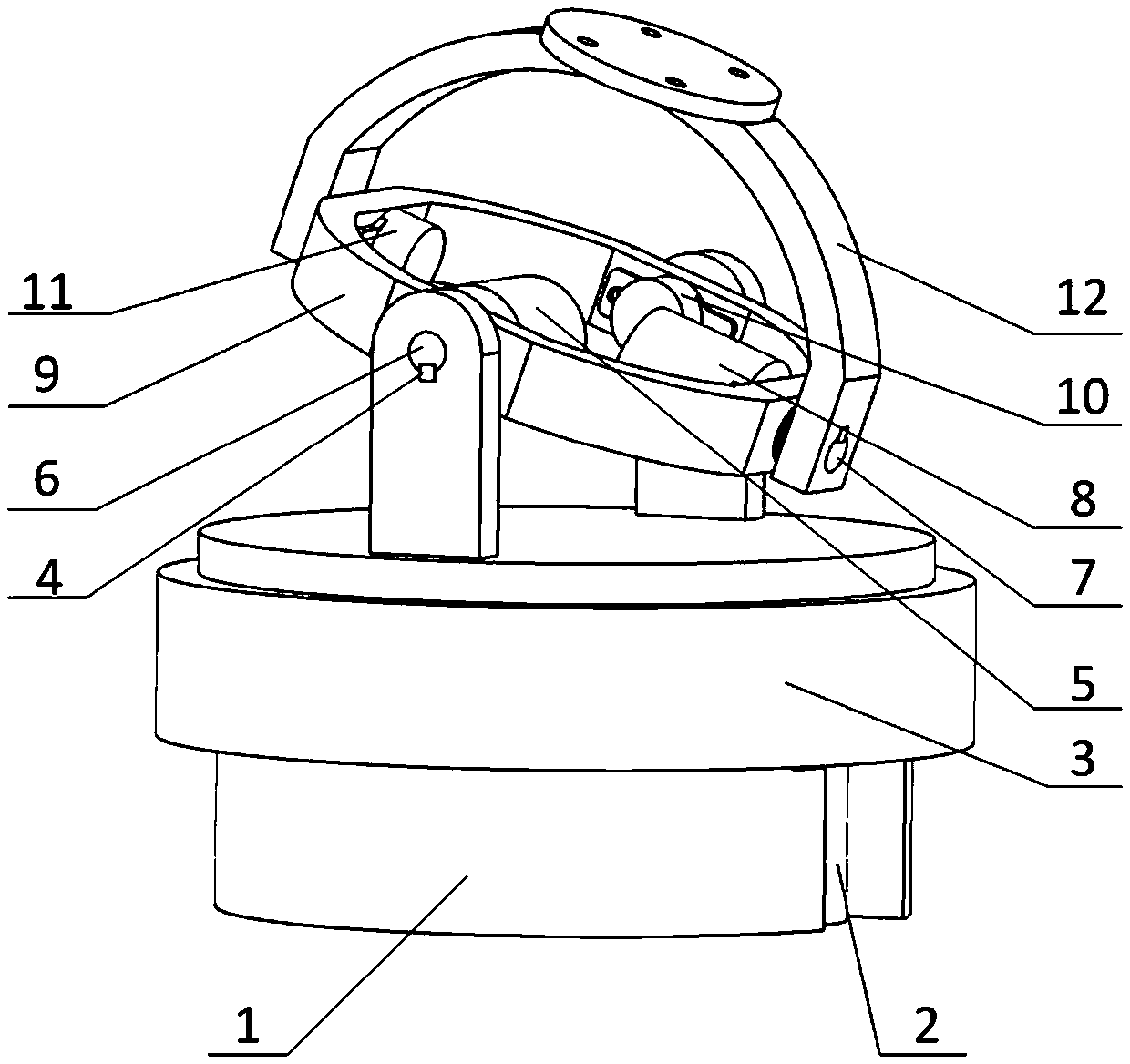
[0021] Specific implementation mode one: combine Figure 1-Figure 7 To describe the embodiment of the present invention in detail, a hydraulic direct-drive three-degree-of-freedom spherical wrist without a singular configuration in this embodiment includes a fixed block 1, a first-stage hydraulic motor 2, a rotating disc 3, a first-stage angle sensor 13, Rotating ring 9, second-stage hydraulic motor 5, second-stage angle sensor 10, third-stage hydraulic motor 8, third-stage angle sensor 11, and rotating semicircular ring 12.

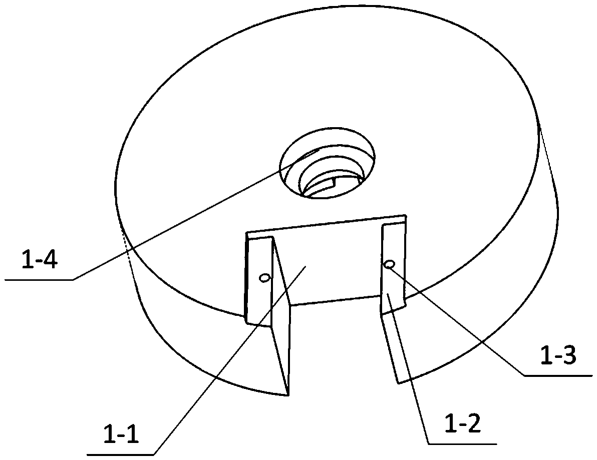
[0022] like image 3 , Figure 4 As shown, the fixed block 1 includes a hydraulic motor groove 1-1, a flange groove 1-2, a motor threaded hole 1-3, a fixed block bearing groove 1-4, a fixed threaded hole 1-5, and a wire groove 1-6 , the first stage hydraulic motor is placed in the hydraulic motor slot 1-1, the first stage hydraulic motor flange 15 is fixedly connected with the threaded hole 1-3 on the fixed block 1 through screws, and the first stage h...

specific Embodiment approach 2

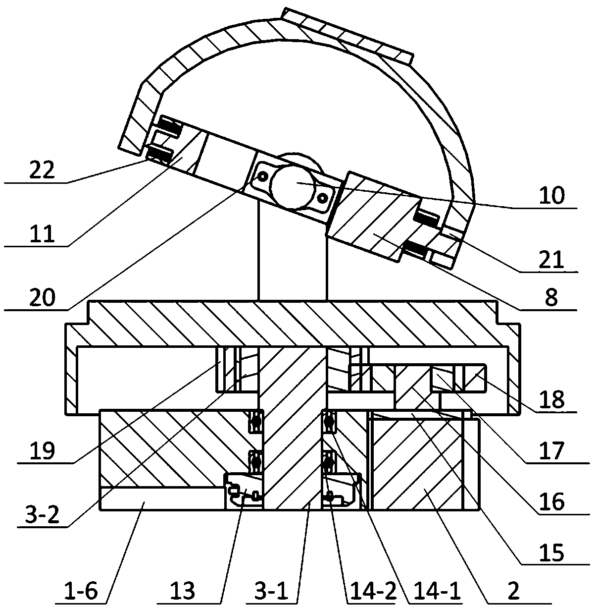
[0025] Specific implementation mode two: combination figure 2 Describe the embodiment of the present invention, a hydraulic direct-drive three-degree-of-freedom spherical wrist without singular configuration in this embodiment has a vertical through hole in the middle of the fixed block 1, and the fixed block bearing grooves 1-4 are arranged in the middle of the fixed block 1. In the through hole, an upper bearing 14-1 and a lower bearing 14-2 are arranged in the fixed block bearing groove 1-4, and the rotating shaft 3-1 is rotationally connected with the fixed block 1 through the upper bearing 14-1 and the lower bearing 14-2, and the rotating shaft 3 The shaft shoulder of -1 pushes on the inner ring of the upper bearing 14-1, and the lower end of the rotating shaft 3-1 is connected with the first-level angle sensor 13, and the first-level angle sensor 13 is also fixedly connected with the fixed block 1 by screws.

specific Embodiment approach 3

[0026] Specific implementation mode three: combination figure 1 and figure 2 Describe the embodiment of the present invention. In the hydraulic direct drive three-degree-of-freedom spherical wrist of this embodiment, the second-stage hydraulic motor shaft 6 is connected with the first fixed key 4 and the first shaft hole 3-6. The rod 3-4 is fixedly connected, the second-stage hydraulic motor shaft 6 and the rotating ring 9 are rotationally connected through bearings, the shaft of the second-stage angle sensor 10 is inserted into the first shaft 3-5 to form a fixed connection, and the first shaft 3-5 It is rotatably connected with the rotating annulus 9 through a bearing.


PUM


Abstract

The invention discloses a three-degree-of-freedom spherical wrist based on hydraulic direct drive without singular configuration. The three-degree-of-freedom spherical wrist comprises a fixed block, an angle sensor, hydraulic motors, a rotating disc, a rotating ring and a rotating half ring. The fixed block is used for fixing the first-stage hydraulic motor. The rotating disc is rotationally connected to the fixed block through a bearing. The rotating disc and the first-stage hydraulic motor are in gear transmission. The rotating ring and the rotating disc are rotationally connected by the bearing. The second-stage hydraulic motor and the angle sensor are fixed on the inner side of the rotating ring. A shaft of the second-stage hydraulic motor penetrates an inner ring of the bearing and is fixedly connected to the rotating disc. The connection between the rotating half ring and the rotating ring is the same as the connection between the rotating ring and the rotating disc. By the adoption of the three-degree-of-freedom spherical wrist, the hydraulically driven three-degree-of-freedom spherical wrist movement does not have the singular configuration, a high-precision reducer does not need to be used and the three-degree-of-freedom spherical wrist has a series of advantages of the simple and compact structure, high power density, high load/self-weight ratio, strong bearing capacity and the like.

Description

technical field [0001] The invention relates to the field of robots, in particular to a hydraulically driven three-degree-of-freedom spherical wrist for an industrial robot without a singular configuration. Background technique [0002] Industrial robot (manipulator) is an important supporting technology of a country's advanced manufacturing industry and an important production equipment in an information society. It is of great significance to social development and enhancing military and national defense strength. Another strategic emerging industry. [0003] The wrist unit connects the robotic arm and the end effector, and its main function is to adjust the spatial attitude of the end effector to meet the job requirements. The wrist unit has an important influence on the positioning accuracy and space attitude control performance of the end effector, and its performance has become one of the main factors restricting the application of robots, and has become an important ...

Claims


Application Information

Patent Timeline
IPC IPC(8): B25J17/02
CPCB25J17/0275
Inventor 汪成文张震阳陈帅吉鑫浩权龙
Owner TAIYUAN UNIV OF TECH
Why Eureka
Try Eureka