[0025] In order to make the objectives, technical solutions, and advantages of the present invention clearer, the following further describes the present invention in detail with reference to the accompanying drawings and specific embodiments. It should be understood that the specific embodiments described herein are only used to explain the present invention, but not to limit the present invention.
[0026] In order to make the description of the present disclosure more detailed and complete, the following provides an illustrative description for the embodiments and specific examples of the present invention; this is not the only way to implement or use the specific embodiments of the present invention. The implementation manners cover the characteristics of a number of specific embodiments and the method steps and sequences used to construct and operate these specific embodiments. However, other specific embodiments can also be used to achieve the same or equal functions and sequence of steps.
[0027] The embodiment of the present invention discloses an integrated air-conditioning propulsion system. Compared with the existing air-conditioning propulsion system, the propellant management device, the propulsion device, and the addition and discharging device all adopt a built-in design and are packaged in a storage box, saving Eliminating the connecting pipes between the devices makes the structure more compact, reduces the occupied space, and makes the connection more stable and reliable. The propellant management device connects the liquid cavity and the air cavity, and controls the isolation or communication between the liquid cavity and the air cavity. When connected, the propellant management device controls the liquid R134a single-component propellant to be converted into the gaseous R134a single-component propellant, and the gaseous The R134a single-component propellant is output to the air cavity to ensure that the R134a single-component propellant in the air cavity is pure gaseous and achieves higher propulsion efficiency. In addition, the system reduces external installation interfaces and connects to the satellite through screw holes, which is convenient and quick, and achieves precise control in satellite attitude adjustment and orbit adjustment.
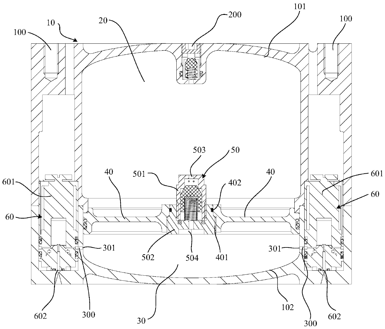
[0028] figure 1 Shows an integrated air-conditioning propulsion system, see figure 1 The R134a single-component propellant used in the system has two states: liquid and gas; the system includes: tank 10, liquid cavity 20, air cavity 30, partition 40, propellant management device 50 and propulsion device 60. Among them, the storage tank 10 has an upper chamber 101 and a lower chamber 102 arranged in sequence; the liquid chamber 20 is located in the upper chamber 101 for storing liquid R134a single-component propellant; the air chamber 30 is located in the lower chamber 102, For storing gaseous R134a single-component propellant, the gas cavity 30 has an output end 301; the lower chamber 102 is provided with a partition 40, which is located between the liquid cavity 20 and the air cavity 30, and the liquid cavity 20 and the air cavity 30 isolation, used to fix the propellant management device 50; the propellant management device 50 is set in the storage tank 10, connected to the liquid cavity 20 and the air cavity 30, and used to control the isolation or communication between the liquid cavity 20 and the air cavity 30. When connected, the propellant The management device 50 controls the conversion of the liquid R134a single-component propellant to the gaseous R134a single-component propellant, and outputs the gaseous R134a single-component propellant to the output end 301 of the air chamber 30; in the liquid chamber 20 and the air chamber 30 When the pressure difference between is less than the preset pressure difference threshold, the propellant management device 50 isolates the liquid cavity 20 and the air cavity 30. When the pressure difference between the liquid cavity 20 and the air cavity 30 is greater than the preset pressure difference threshold, the propellant management The device 50 connects the liquid cavity 20 and the air cavity 30, vaporizes the R134a single-component propellant in the liquid cavity 20 and outputs it to the air cavity 30; the propulsion device 60 is arranged inside the tank 10 and is connected to the output end 301 of the air cavity 30 It is connected to eject the gaseous R134a single-component propellant output from the output end 301 of the air cavity 30 to provide the thrust and impulse required by the satellite.
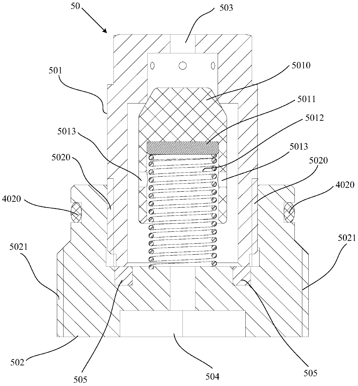
[0029] Further, see figure 1 with figure 2 , The propellant management device 50 includes: a valve seat 501 and a spring seat 502, the valve seat 501 is located at the upper end of the spring seat 502, the inner side of the spring seat 502 is provided with a first screw block 5020, the valve seat 501 passes through the first screw block 5020 It is screwed with the spring seat 502 to fix the valve seat 501 on the spring seat 502. The valve seat 501 and the spring seat 502 are screwed together, which is convenient for installation and disassembly, and is convenient for maintenance. The propellant management device 50 is built-in packaged inside the storage tank 10 and connects the air cavity 30 and the liquid cavity 20 through the valve seat The 501 and the spring seat 502 realize the isolation and communication between the liquid chamber 20 and the air chamber 30, instead of the traditional conduit type connection, save the connection pipeline between the devices, reduce the installation interface, save the occupied space and make the structure more compact. It can effectively prevent the propellant from leaking, avoid the loss of propellant power, and ensure that the R134a single-component propellant in the air cavity 30 is pure gaseous to achieve higher propulsion efficiency.
[0030] Further, see figure 2 , The valve seat 501 is provided with a valve core 5010, an adjusting gasket 5011 and a spring 5012. The upper end of the valve core 5010 contacts the valve seat 501 to form a valve. The adjusting gasket 5011 is arranged between the valve core 5010 and the spring 5012. To adjust the opening pressure of the valve, one end of the spring 5012 is connected to the adjusting washer 5011, and the other end of the spring 5012 is connected to the spring seat 502; when the pressure difference between the liquid chamber 20 and the air chamber 30 is less than the preset pressure difference threshold, the spring 5012 Freely expand and contract until the upper end of the valve core 5010 contacts the valve seat 501, the propellant management device 50 isolates the air chamber 30 from the liquid chamber 20, and the pressure difference between the liquid chamber 20 and the air chamber 30 is greater than the preset pressure difference threshold , The valve core 5010 is subjected to unbalanced pressure, and the spring 5012 is squeezed to separate the upper end of the valve core 5010 from the valve seat 501. The propellant management device 50 connects the liquid chamber 20 and the air chamber 30 to connect the liquid in the liquid chamber 20 The R134a single-component propellant is converted into gaseous R134a single-component propellant, and is output into the air cavity 30.
[0031] Specifically, when the pressure difference of the propellant management device 50 is less than the preset pressure difference threshold, the propellant management device 50 isolates the air cavity 30 from the liquid cavity 20, and the propellant management device 50 restrains the liquid R134a single-component propellant in the liquid. Cavity 20. In the process of gas consumption in the gas chamber 30, the pressure of the gas chamber 30 drops, and the pressure difference between the gas chamber 30 and the liquid chamber 20 gradually increases. When the pressure difference strength increases to the extent that the spring 5012 is deformed, the liquid R134a single element The propellant enters the propellant management device 50, and uses the principle of liquefied gas flash evaporation to convert the liquid R134a single-component propellant into gaseous R134a single-component propellant and bind the gaseous R134a single-component propellant to the air cavity 30 During this process, the intensity of the pressure difference gradually weakens. After the intensity is reduced to less than the preset pressure difference threshold, the propellant management device 50 isolates the gas cavity 30 from the liquid cavity 20 again, and the gas cavity 30 is full of gas. The preset pressure difference threshold in this embodiment can be adjusted by adjusting the thickness of the gasket 5011. The thicker the adjustment gasket 5011, the greater the compression of the spring 5012. The controlled pressure difference between the liquid chamber 20 and the air chamber 30 Bigger.
[0032] In this system, the air cavity 30 ensures sufficient gas-liquid conversion, ensuring that the propellant in the air cavity 30 is pure gas, and achieving higher propulsion efficiency.
[0033] Further, see figure 2 , The valve core 5010 is provided with two symmetrical through holes 5013, which are used to connect the liquid chamber 20 and the air chamber 30 when the lower end surface of the valve core 5010 moves to abut the spring seat 502, avoiding the lower end surface of the valve core 5010 and The spring seat 502 forms a seal, so that the liquid R134a monopropellant in the liquid cavity 20 cannot enter the air cavity 30.
[0034] Further, see figure 1 , The outer side of the spring seat 502 is provided with a second screw block 5021, the partition 40 is screwed to the spring seat 502 through the second screw block 5021, and the propellant management device 50 is fixed on the partition 40, the propellant management device 50 The screw connection with the partition 40 is convenient for installation and disassembly, and convenient for maintenance.
[0035] Specifically, see figure 1 with figure 2 The partition plate 40 has a threaded portion 401 that is screwed to the spring seat 502 and an abutment portion 402 that abuts on the spring seat 502. The abutment portion 402 is provided with a sealing ring 4020, and the liquid cavity 20 and the air cavity are separated by the sealing ring 4020. 30 are isolated from each other to prevent the liquid propellant from leaking into the air cavity 30 through the second screw block 5021 from the liquid cavity 20 before the valve core 5010 is opened.
[0036] Further, see figure 1 with figure 2 The propellant management device 50 is provided with a liquid propellant inlet 503 located above and a gaseous propellant outlet 504 located below. The liquid R134a single-component propellant inlet 503 is connected to the liquid cavity 20, and the gaseous propellant outlet 504 is connected to the gas cavity 30 connected.
[0037] Further, see figure 2 A sealing gasket 505 is provided between the spring seat 502 and the valve seat 501.
[0038] Further, see figure 1 The propulsion device 60 includes a solenoid valve 601 and a cold air propulsion panel (not shown in the figure). The solenoid valve 601 is connected to the output end 301 of the air chamber 30. The cold air propulsion panel is detachably connected to the output end 301 of the solenoid valve 601. The solenoid valve 601 controls the ejection of gaseous R134a single-component propellant to the cold air propellant, and the cold air propellant ejects the gaseous R134a single-element propellant.
[0039] Further, see figure 1 The output end 301 of the air cavity 30 is provided with a plurality of air cavity passages 300, and the solenoid valve 601 is connected to the air cavity 30 through the air cavity passage 300.
[0040] Specifically, a cold air propulsion panel can be connected to one or more solenoid valves 601. One solenoid valve 601 has multiple air inlets. Each air inlet is connected to the air cavity 30 through the air cavity passage 300. The propulsion device 60 is completed according to The requirements for attitude control and orbit maintenance and control of the satellite at various stages determine the number of solenoid valves 601 connected to the air-conditioning propulsion panel 602, and determine the position and layout of each solenoid valve 601 in the system. The air-conditioning propulsion panel is equipped with a nozzle 602, and the solenoid valve 601 is equipped with a nozzle connected to the air inlet. The nozzle 602 is connected with the nozzle. The air-conditioning propulsion panel with different apertures of the nozzle 602 can be replaced according to the required impulse. The gaseous R134a single The component propellant is output from the output end 301 of the air chamber 30 to the nozzle of the solenoid valve 601, and the gaseous R134a single component propellant is ejected from the nozzle 602 of the cold air propulsion panel to provide the thrust and impulse required by the satellite.
[0041] During the operation of the system, in one or more solenoid valves 601 controlled by the satellite's control system, when the demand impulse is small, the solenoid valve 601 opens and closes periodically, and sprays gaseous R134a single-component propellant , The system is in pulse propulsion mode. In one or more solenoid valves 601 controlled by the satellite's control system, when the demand impulse is large, the solenoid valve 601 is normally open and sprays gaseous R134a single-component propellant. It is in continuous propulsion mode. In this mode, the air impulse injected by each solenoid valve 601 is controlled in real time by the control system on the satellite.
[0042] Further, see figure 1 The system also includes an adding and discharging device 200, which is arranged at the top of the liquid chamber 20, and is used for filling and discharging liquid R134a single-component propellant.
[0043] Furthermore, the system can also be equipped with peripheral components (not shown in the figure) as required, such as pressure sensors and temperature sensors.
[0044] Further, a plurality of screw holes 100 are provided on the storage box 10 for connecting with the satellite. This setting method does not require each component in the system to be fixed to the satellite individually, reduces the installation interface between the system and the satellite, facilitates the docking, and improves the connection stability.
[0045] In this embodiment, R134a (1,1,1,2-tetrafluoroethane) single-component propellant has the following advantages:
[0046] a. Green, non-toxic, safe and environmentally friendly: non-flammable, non-explosive, non-irritating, non-corrosive, and does not destroy the ozone layer;
[0047] b. Good stability at room temperature and easy to manage: easy to liquefy (saturated vapor pressure at 20°C at room temperature is 0.57MPa), the system is small in size, and there is not much cold air storage, and the propellant is compressed into a liquid under a limited volume Storage, it is convenient for the propellant to be stored in the limited-volume storage tank 10; it is easy to vaporize (boiling point at 101.3kPa is -26.1℃), and the heating power requirement is low. It can ensure that the propellant in the air cavity 30 is pure gaseous, achieving higher propulsion effectiveness;
[0048] c. Low cost and easy to obtain;
[0049] d. The specific impulse of the propellant in this system is large, and it produces a larger thrust at room temperature. As compared with nitrogen, butane and liquid ammonia, the gas molecular weight of the propellant is large, and the speed of spraying at the nozzle 602 after vaporization It improves the propulsion efficiency of the entire air-conditioning propulsion system.
[0050] The air-conditioning propulsion system has high control accuracy and high system reliability, and can be self-pressurized to realize propellant extrusion and delivery.
[0051] Further, the control method of the system includes:
[0052] When the demand impulse is less than the preset impulse threshold, the propellant management device binds the liquid R134a single-component propellant in the liquid cavity, and the propulsion device performs periodic work. The propellant sprays gaseous R134a single-component propellant in pulse mode Advancing mode
[0053] At this time, the gaseous R134a single-component propellant accumulated and evaporated in the air cavity is supplied to the solenoid valve, which opens and closes periodically, and the solenoid valve injects the gaseous R134a single-component propellant in a pulsed propulsion mode.
[0054] When the demand impulse is greater than the preset impulse threshold, due to the loss of the gaseous R134a single-component propellant, the pressure in the air cavity drops, and the liquid R134a single-component propellant flows over the propellant management device and turns the liquid R134a single-component propellant. The meta-propellant vaporizes to form a gaseous R134a single-component propellant, and the propulsion device performs continuous work. The propelling device is in a continuous propulsion mode when it ejects the gaseous R134a single-component propellant.
[0055] When the gaseous R134a single-component propellant is consumed to the preset pressure difference threshold between the air cavity and the liquid cavity, the liquid R134a single-component propellant flows through the propellant management device and vaporizes the liquid R134a single-component propellant. For the gaseous R134a single-component propellant, the solenoid valve is normally open, and the solenoid valve sprays the gaseous R134a single-component propellant in continuous propulsion mode.
[0056] The above are only the preferred embodiments of the present invention and are not intended to limit the present invention. Any modification, equivalent replacement and improvement made within the spirit and principle of the present invention shall be included in the protection of the present invention. Within range.