A phase change energy storage device

A phase-change energy storage and phase-change unit technology, which is used in thermal storage equipment, lighting and heating equipment, indirect heat exchangers, etc. question

Active Publication Date: 2020-06-26
BEIJING INST OF RADIO MEASUREMENT
View PDF3 Cites 0 Cited by
  • Summary
  • Abstract
  • Description
  • Claims
  • Application Information

AI Technical Summary

Problems solved by technology

[0003] Existing phase-change energy storage devices are generally composed of a cavity and phase-change materials. The shape of the cavity is fixed. The heat that the phase-change energy storage device can store depends on the size of the cavity and the phase-change material inside. Most of the satellites When power equipment is working, it releases a lot of heat. To absorb such a large thermal image, it is necessary to install a larger-sized phase-change energy storage device. In satellite design, it is necessary to reduce the weight and size of the equipment as much as possible, and to install a large-sized phase-change energy storage device. The energy device does not meet the needs of the current satellite design, and the small-sized phase-change energy storage device cannot absorb such a large amount of heat, which cannot meet the heat dissipation requirements, and may easily cause damage to the equipment due to excessive ambient temperature

Method used


Image

  • A phase change energy storage device
  • A phase change energy storage device

Examples


Embodiment Construction

[0029] In order to make the object, technical solution and advantages of the present invention clearer, the present invention will be further described in detail below in conjunction with the accompanying drawings.

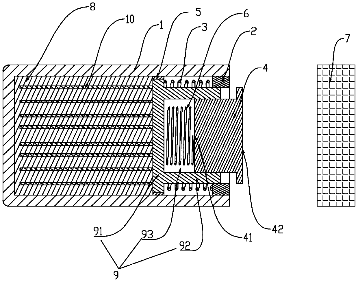
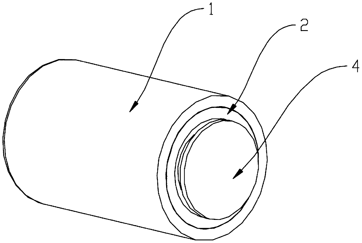
[0030] Such as figure 1 , figure 2 As shown, the phase-change energy storage device disclosed in the present invention includes a heat-conducting piston chamber 1, a phase-change unit 8, a heat-conducting piston 9, a limiting ring 2, a first spring 3, a heat-conducting cap 4, and a heat sink 7. The piston chamber 1 and the heat sink 7 are arranged oppositely on the front and rear surfaces respectively, the heat sink 7 is in front of the piston chamber 1, the piston chamber 1 is a hollow cylinder, the front end of the piston chamber 1 is open and the rear end is sealed, and the piston 9 is inside the piston chamber 1 Slidingly matched with the piston chamber 1, the piston 9 is dynamically sealed with the inner wall of the piston chamber 1.

[0031] The piston 9 ...


PUM


Abstract

The invention discloses a phase-change energy storage device. The phase-change energy storage device comprises a heat conduction piston cavity, a phase-change unit, a heat conduction piston, a limiting ring, a first spring, a heat conduction cap and a heat sink; the piston cavity and the heat sink are oppositely arranged on the front surface and the rear surface, the heat sink is arranged in front of the piston cavity, the front end of the piston cavity is open, and the rear end of the piston cavity is sealed; the piston is in sliding fit in the piston cavity, and the piston is in dynamic sealing with the inner wall of the piston cavity; the phase-change unit is filled in a cavity defined by the end part of the rear end of the piston and the piston cavity, the limiting ring is fixedly connected with the inner wall of the front end of the piston cavity, and the first spring is arranged between the limiting ring and the piston; and the two ends of the first spring are respectively abutted against the limiting ring and the piston, the heat conduction cap is connected with the front end of the piston, the front end of the heat conduction cap penetrates out of the piston cavity, and the heat sink is arranged in front of the heat conduction cap. The phase-change energy storage device can dissipate heat generated by high-power equipment on the basis of keeping a small size, the problem of thermal control of the high-power equipment on a satellite is solved, and normal operation of the equipment is guaranteed.

Description

technical field [0001] The invention relates to the field of thermal energy storage, in particular to a phase change energy storage device. Background technique [0002] In the vacuum environment of space, the heat of the satellite can only be transferred through heat conduction and heat radiation. During the orbiting process of the satellite, the temperature changes greatly. It is necessary to set up a thermal control system to control the temperature of the working equipment on the satellite within a reasonable range. , thus, the phase change energy storage device can be set to store and provide thermal energy. [0003] Existing phase-change energy storage devices are generally composed of a cavity and phase-change materials. The shape of the cavity is fixed. The heat that the phase-change energy storage device can store depends on the size of the cavity and the phase-change material inside. Most of the satellites When power equipment is working, it releases a lot of heat...

Claims


Application Information

Patent Timeline
Patent Type & Authority Patents(China)
IPC IPC(8): F28D20/02F28F13/00
CPCF28D20/02F28F13/00F28F2013/008Y02E60/14
Inventor 廖全文刘晓红李培培陈彦
Owner BEIJING INST OF RADIO MEASUREMENT
Why Eureka
Try Eureka