High-speed aircraft capable of achieving drag reduction and range extension

A high-speed aircraft and cover technology, applied in the types of weapons, offensive equipment, projectiles, etc., can solve the problems of inability to find a solution, large resistance of missiles and aircraft, and reduce resistance, improve the effect of drag reduction, and avoid turbulence. Effect

Active Publication Date: 2019-09-24
石家庄市居高科技有限公司
View PDF17 Cites 0 Cited by
  • Summary
  • Abstract
  • Description
  • Claims
  • Application Information

AI Technical Summary

Problems solved by technology

[0002] Due to the influence of air resistance, the range of the shells or missiles currently used for launching is only 1 / 3 of the theoretical range of vacuum, and most of the kinetic energy of the projectile is consumed by air resistance. In order to reduce air resistance and increase the range, people carry out Various studies have been carried out, but no satisfactory solution has been found. The artillery shells, missiles and aircraft in the prior art still have the problem of high resistance.

Method used


Image

  • High-speed aircraft capable of achieving drag reduction and range extension
  • High-speed aircraft capable of achieving drag reduction and range extension
  • High-speed aircraft capable of achieving drag reduction and range extension

Examples


Embodiment 1

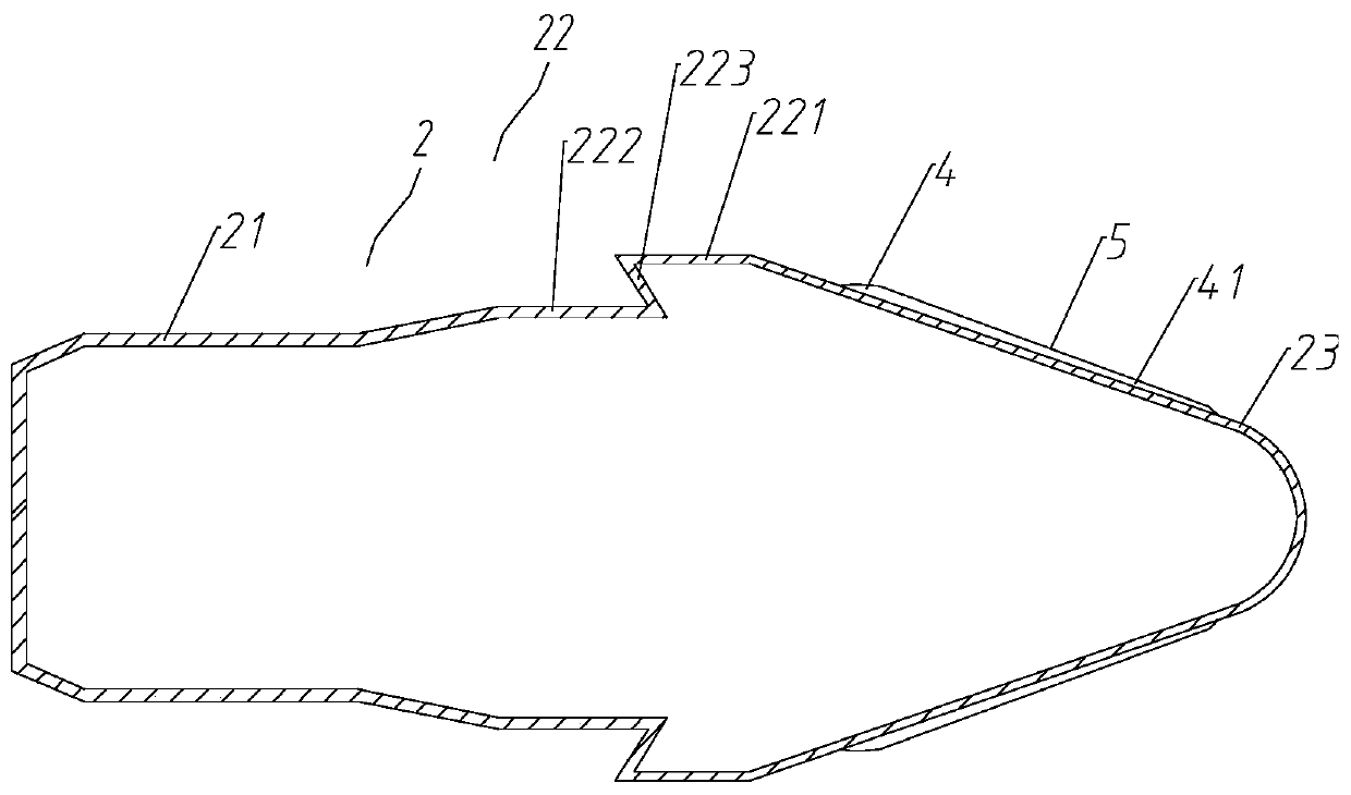
[0032] Such as Figure 1 ~ Figure 2 As shown, the present invention proposes a drag-reducing and range-extending high-speed aircraft, including

[0033] The main housing 2, the main housing 2 includes a tail housing 21, a platform stage 22, and a head housing 23 that are connected in sequence and are all cylindrical. The front end of the head housing 23 is tapered.

[0034] The head shell 23 is provided with a cylindrical cover body 3 coaxial with the head shell 23, the front end of the cover body 3 is conical, and a channel 4 is formed between the cover body 3 and the head shell 23. The channel 4 is divided into several first strip-shaped channels 41 parallel to each other by the first ribs 5, one side of the first ribs 5 is connected with the inner wall of the head housing 23, and one side is connected with the inner wall of the cover body 3, The front end of the first strip channel 41 is an inlet 6, and the tail end is an outlet 7, and the outlet 7 is close to the platform...

Embodiment 2

[0045] Including all the structures in Example 1, at the same time, the first rib 5 and the second rib 8 are helical, and the direction of rotation is consistent with the surface precession direction when the projectile is flying, thus becoming a helical rib precession scheme, adjacent to the second rib The parts of the two ribs 8 close to the cover body 3 are in contact with each other, and are in the shape of closely arranged teeth, which can better achieve the effect of reducing drag.

Embodiment 3

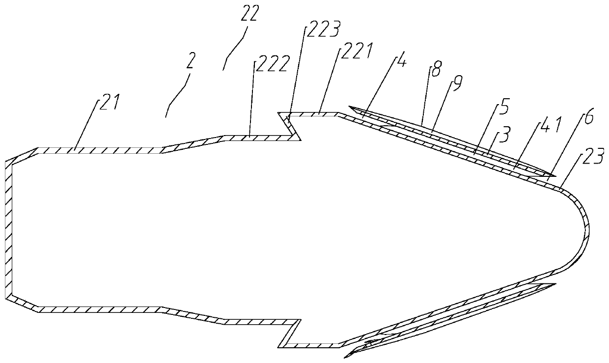
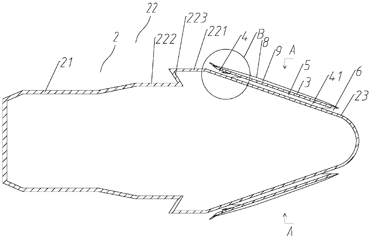
[0047] Such as Figure 3 ~ Figure 5 As shown, a kind of drag-reducing and range-extending high-speed aircraft proposed by the present invention includes all the structures of embodiment 1,

[0048] Further, the length of the first strip-shaped passage 41 is 1 / 2 to 3 / 4 of the length of the second strip-shaped passage 9 .

[0049] Further, the inner wall of the end of the cover body 3 near the outlet 7 is provided with a cylindrical variable-diameter spoiler 10, the diameter of the variable-diameter spoiler 10 gradually decreases from the front end to the rear end, and the outer wall of the variable-diameter spoiler 10 is in contact with the cover. A suction flow space 11 is formed between the inner walls of the body 3 , and a through hole 12 is provided on the cover body 3 , and the through hole 12 communicates with the flow suction space 11 and the second strip-shaped channel 9 .

[0050] Further, the tail of the cover body 3 is also connected with a diameter-reducing body 13...


PUM


Abstract

The invention belongs to the technical field of aircrafts such as cannonballs and guided missiles, and provides a high-speed aircraft capable of achieving drag reduction and range extension. The aircraft comprises a main casing, wherein the main casing comprises a tail casing, a stage, a head casing, and the tail casing, the stage and the head casing are connected in sequence and are all cylindrical; the front end part of the head casing is conical, the head casing is provided with a cover body which is coaxial with the head casing and is of a cylindrical shape, and the front end part of the cover body is conical; a channel is formed between the cover body and the head casing, and the channel is divided into a plurality of first strip-shaped channels which are parallel to one another through first ridges; one side edge of each first ridge is connected with the inner wall of the head casing, and the other side edge of each first ridge is connected with the inner wall of the cover body; the front end of the first strip-shaped channel is provided with an inlet, the tail end is provided with an outlet, and the outlet is close to the stage; and a plurality of circumferentially arranged second ridges are arranged on the outer wall of the cover body, and a second strip-shaped channel is formed between every two adjacent second ridges. According to the high-speed aircraft, the problem of large resistance of the cannonballs, the missiles and the aircrafts is solved, and the air resistance of the aircraft can be reduced by 35% or above.

Description

technical field [0001] The invention belongs to the technical field of aircraft such as artillery shells and missiles, and relates to a high-speed aircraft with ribs prefabricated on the surface of the high-speed aircraft to reduce air resistance and increase range. The invention is also applicable to torpedoes in water. Background technique [0002] Due to the influence of air resistance, the range of the shells or missiles currently used for launching is only 1 / 3 of the theoretical range of vacuum, and most of the kinetic energy of the projectile is consumed by air resistance. In order to reduce air resistance and increase the range, people carry out Various studies have been carried out, but a satisfactory solution cannot be found all the time, and the artillery shells, missiles and aircraft in the prior art still have the problem of large resistance. Contents of the invention [0003] The invention proposes a method to solve the problems in the prior art. [0004] Tec...

Claims


Application Information

Patent Timeline
Patent Type & Authority Applications(China)
IPC IPC(8): F42B10/38F42B10/46
CPCF42B10/38F42B10/46
Inventor 闫保宁闫留全宋守宏周兆海吕洪涛宋海波
Owner 石家庄市居高科技有限公司
Why Eureka
Try Eureka