Novel gauge-changeable bogie track-changing function and reliability test bed
A reliability and test-bed technology, applied in the direction of railway vehicle testing, etc., can solve the problems of changing gauge bogies, etc., and achieve the effects of strong overall bearing capacity, improved reliability and safety, and low motion resistance.
- Summary
- Abstract
- Description
- Claims
- Application Information
AI Technical Summary
Problems solved by technology
Method used
Image

Examples
Embodiment Construction
[0025] Below in conjunction with accompanying drawing, the present invention is described in further detail:
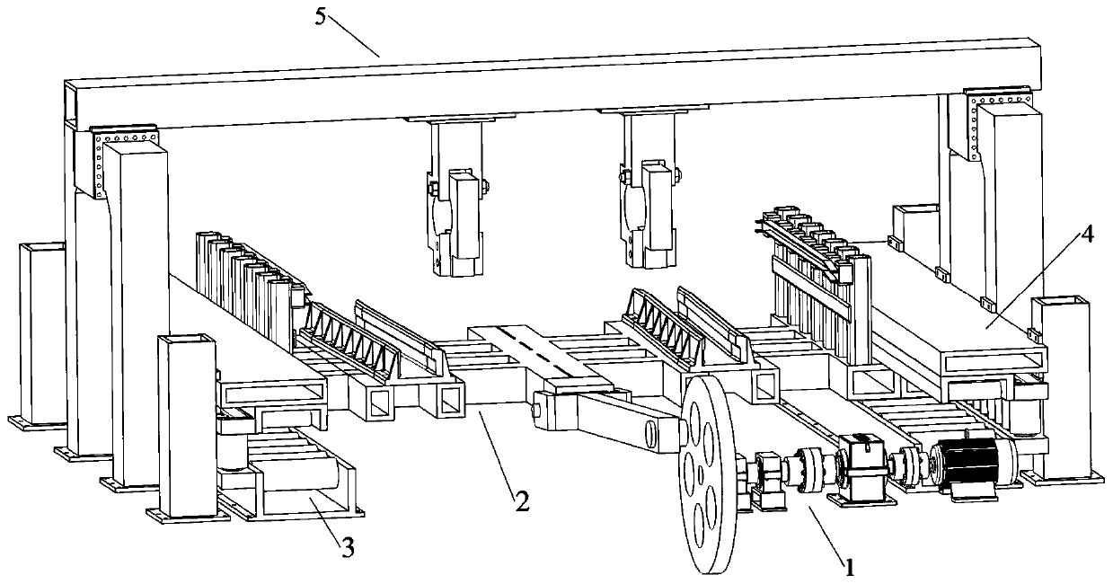
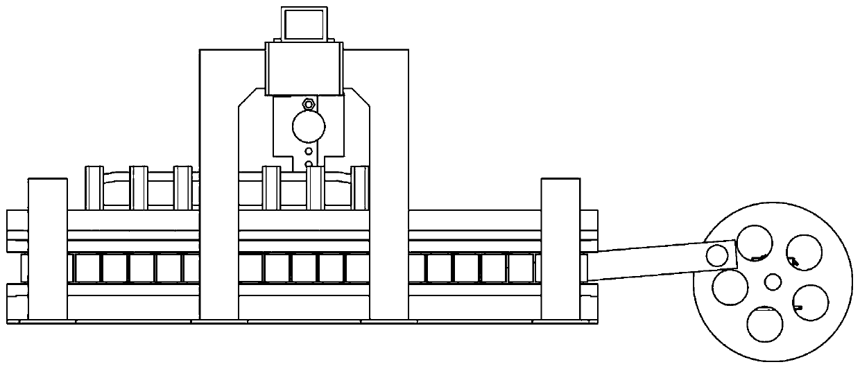
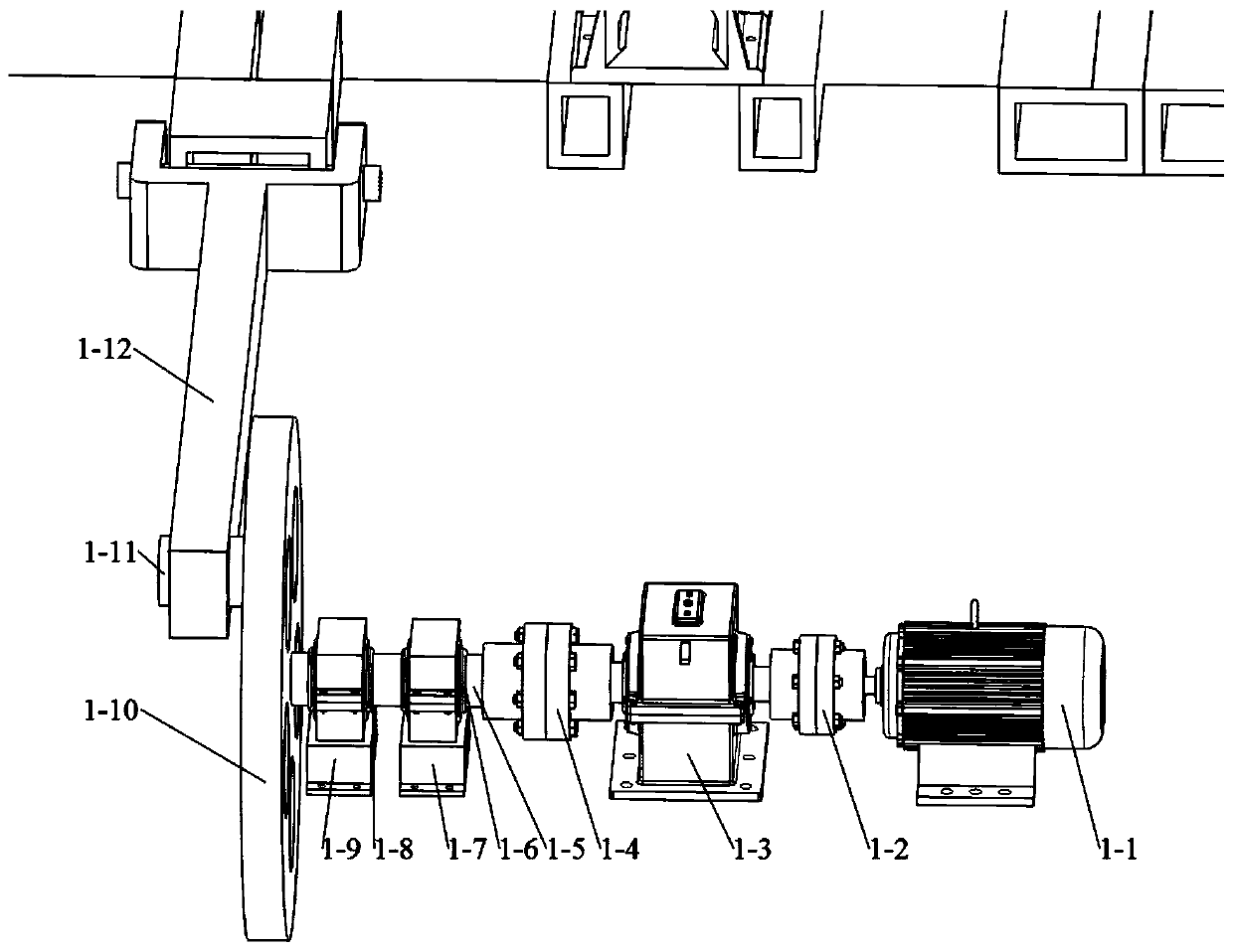
[0026] refer to figure 1 and figure 2 , a new track-gauge bogie track change function and reliability test bench according to the present invention mainly includes a mobile platform power drive device 1, a translational gauge change device 2, a carrying rail 3, a limit device 4, The gantry suspension device 5; the mobile platform power drive device 1 is fixedly installed on the ground, and the longitudinal movement of the translational gauge conversion device 2 is driven by the motor-crank connecting rod motion pair, and the translational gauge conversion device 2 pairs The variable gauge wheelset is unlocked and locked, and provides lateral guidance for the axial gauge variable movement of the wheelset along the wheel shaft; the load-bearing running rail 3 is symmetrically installed under the two sides of the translational gauge changing device 2 , to provide load...
PUM
 Abstract
Description
Claims
Application Information
PatSnap Eureka turns technology decisions into work you can execute. Powered by our Innovation Knowledge Graph, it runs expert workflows across engineering, life sciences, materials and intellectual property. Get your review-ready output in minutes.


