Outer conductor heating cavity for microwave heating non-combustion equipment

A technology of combustion equipment and microwave heating, applied in applications, smoker supplies, tobacco, etc., can solve the problems of limited transmission distance, large microwave transmission loss, loss of portability, etc.

Pending Publication Date: 2019-09-27
YUNNAN TOBACCO BIOLOGICAL TECH CO LTD
View PDF7 Cites 7 Cited by
  • Summary
  • Abstract
  • Description
  • Claims
  • Application Information

AI Technical Summary

Problems solved by technology

[0003] At present, there are two heating methods for low-temperature cigarette-type e-cigarettes. One is to heat the pod through the heating element relying on touch-type heat conduction. When the resistance becomes larger, the resistance temperature will rise higher to effectively heat the pod, so that the resistance temperature may reach 400-500°C. The problem of excessive heating temperature during work will cause the local tobacco temperature in contact with the heating element to be too high, resulting in Partially cracked, releasing substances harmful to the human body
[0004] One is heating by microwaves, but there is a microwave cavity to form effective microwaves because the microwave frequency limitation is difficult to meet the size of the microwave cavity, and the transmission loss of the formed microwaves in the microwave cavity of this size is too large The transmission distance is limited, the tobacco cannot be heated evenly, and it cannot release enough volatile components of tobacco to meet the needs of smokers. The tobacco at a distance can only be heated by conduction, which loses the meaning of microwave heating; and if further Enlarging the diameter of the heating cavity will lose portability and make microwave heating electronic cigarette technology meaningless

Method used


Image

  • Outer conductor heating cavity for microwave heating non-combustion equipment
  • Outer conductor heating cavity for microwave heating non-combustion equipment
  • Outer conductor heating cavity for microwave heating non-combustion equipment

Examples


Embodiment 1

[0060] Embodiment 1: The present invention is used in the outer conductor heating cavity of microwave heating not to burn equipment

[0061] The implementation mode of this embodiment is as follows:

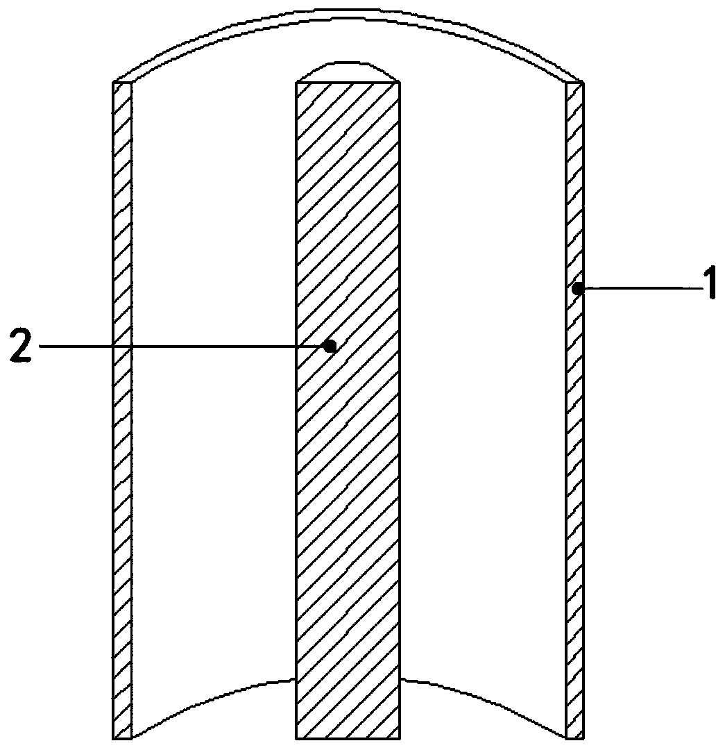
[0062] The outer conductor heating chamber 1 is made of 304 stainless steel material, which is cylindrical and hollow, and its length is longer than that of the inner conductor column 2. The microwave frequency of the solid-state microwave source used is 915MHz.

[0063] Place the outer conductor heating cavity 1 of this embodiment on the periphery of the axis of the inner conductor column 2 of the microwave heating smoking set to obtain a microwave coaxial heating cavity for the microwave heating and non-burning smoking set. For details, refer to the attached figure 1 .

Embodiment 2

[0064] Embodiment 2: The present invention is used in the outer conductor heating cavity of microwave heating not to burn equipment

[0065] The implementation mode of this embodiment is as follows:

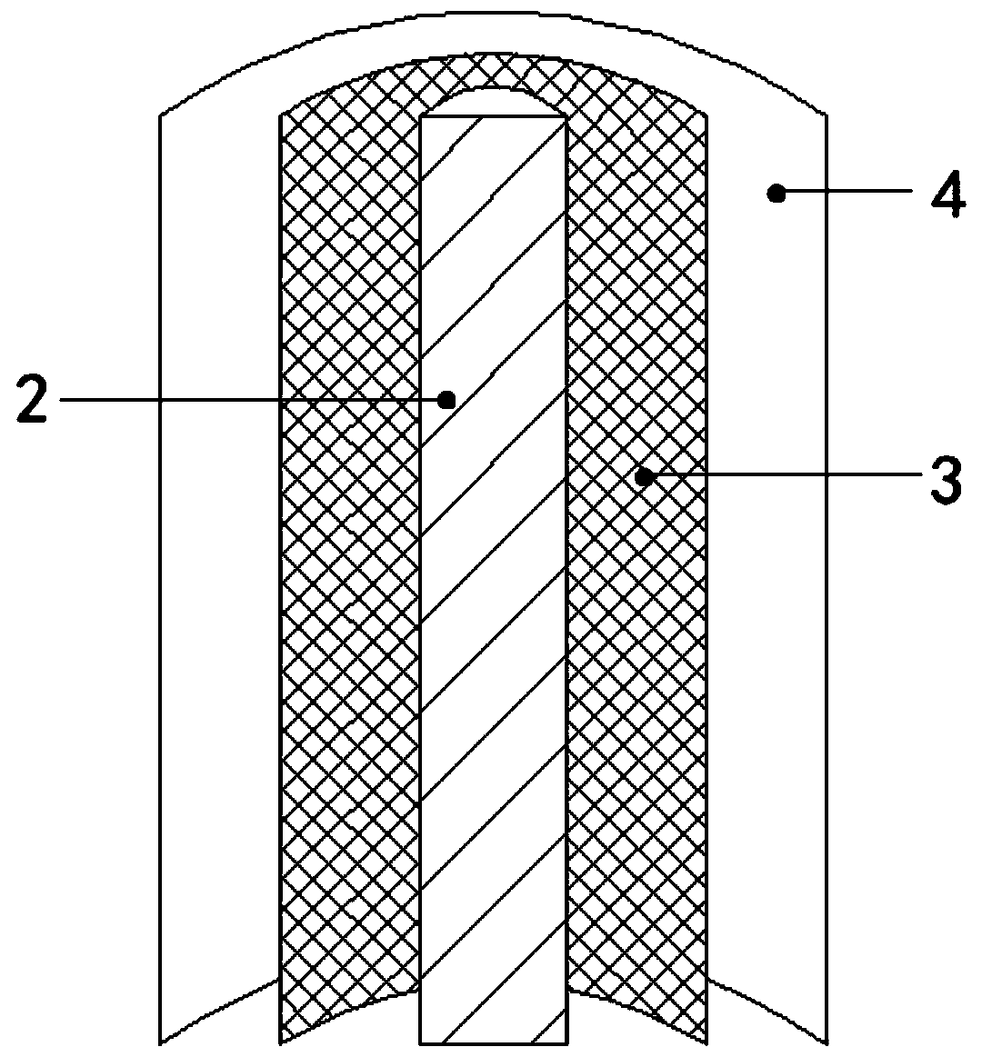
[0066] The outer conductor heating cavity 1 is made of two layers of brass 100-mesh mesh, the diameter of the first layer of outer conductor mesh cavity 3 is slightly smaller than the second layer of outer conductor mesh cavity 4; the outer conductor brass mesh is a cylindrical hollow shape , the length is greater than the length of the inner conductor column 2, and the solid-state microwave source used is 2.45 GHz.

[0067] Place the outer conductor heating cavity 1 of this embodiment on the periphery of the axis of the inner conductor column 2 of the microwave heating smoking set to obtain a microwave coaxial heating cavity for the microwave heating and non-burning smoking set. For details, refer to the attached figure 2 .

Embodiment 3

[0068] Embodiment 3: The present invention is used in the outer conductor heating cavity of microwave heating not to burn equipment

[0069] The implementation mode of this embodiment is as follows:

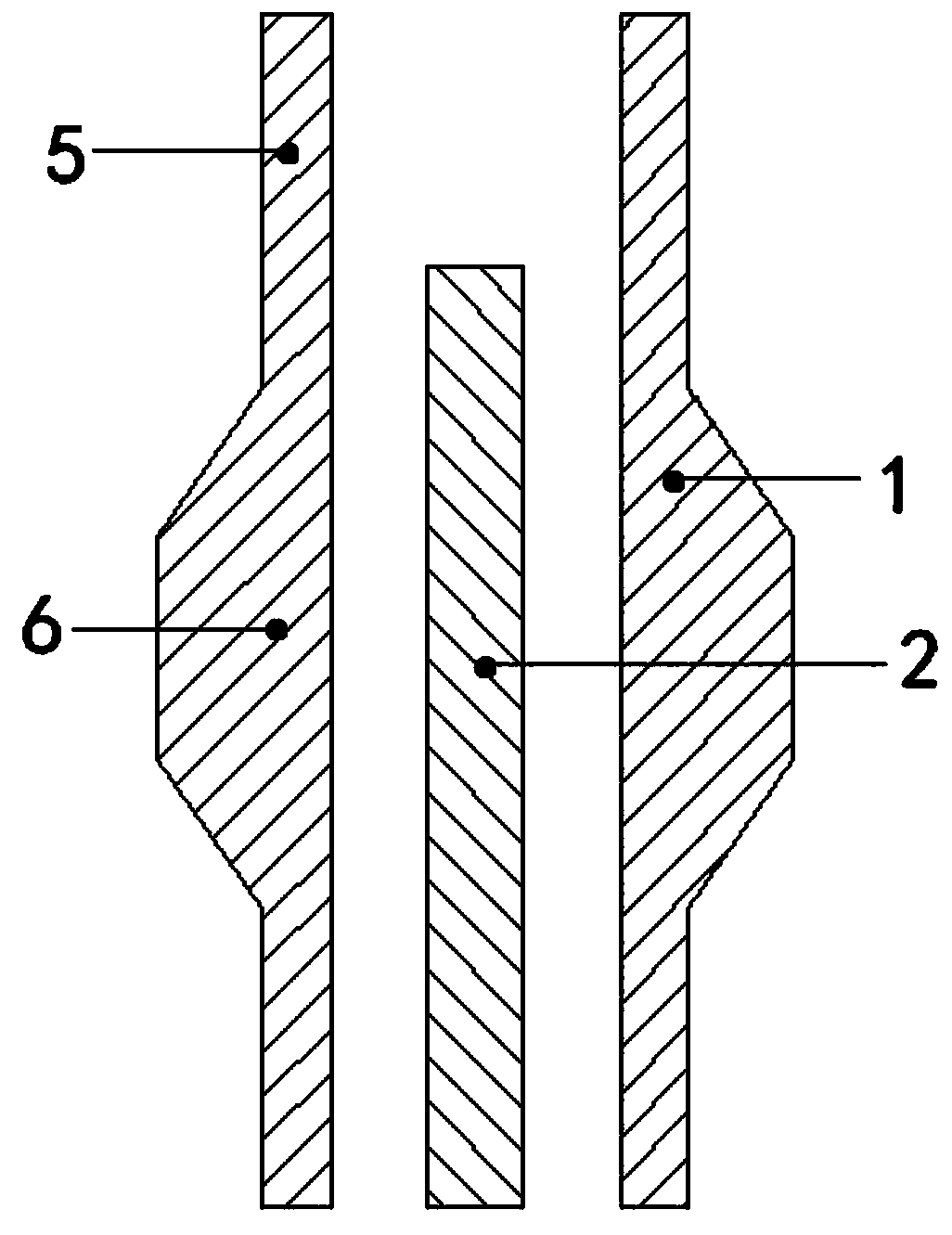
[0070] The outer conductor heating chamber 1 is made of high dielectric constant carbon fiber. The wall thickness of the outer conductor heating chamber 1 is slightly thinner at both ends 5 and the middle part 6 is slightly thicker; the inner wall is a cylindrical hollow shape; the overall length is longer than that of the inner conductor column 2 length, the solid-state microwave source used is 5.8GHz.

[0071] Place the outer conductor heating cavity 1 of this embodiment on the periphery of the axis of the inner conductor column 2 of the microwave heating smoking set to obtain a microwave coaxial heating cavity for the microwave heating and non-burning smoking set. For details, refer to the attached image 3 .


PUM


Abstract

The invention relates to an outer conductor heating cavity for microwave heating non-combustion equipment. The outer conductor heating cavity and an inner conductor column which is coaxially overlapped with the outer conductor heating cavity form a coaxial heating cavity, a microwave source enters the coaxial heating cavity from one end of the inner conductor column for microwave transmission, and the microwave heating of a smoking substrate is realized; and a microwave heating method adopted by outer conductor heating cavity is coaxial microwave heating, so that electromagnetic waves exist between the outer wall of the inner conductor column and the inner wall of the outer conductor heating cavity, the length of the outer conductor heating cavity is larger than the length of the inner conductor column, and the diameter of the outer conductor heating cavity is much smaller than the cutoff wavelength of each frequency. In the absence of the inner conductor column, the microwave attenuation is severe, it is ensured that that no microwave leakage causes harm to a user.

Description

【Technical field】 [0001] The invention belongs to the technical field of heat-not-burn tobacco. More specifically, the present invention relates to an outer conductor heating chamber for microwave heat-not-burn devices. 【Background technique】 [0002] When the cigarette is burned, the temperature will reach 800-900°C. Due to the chemical reaction of tobacco burning, volatilization and thermal cracking, more than 6,000 chemical substances will be released, only a small part of which is originally contained in tobacco and released by heating and volatilization. In addition, more than 4,000 kinds of chemical substances are newly produced after tobacco combustion and thermal cracking, such as polycyclic aromatic hydrocarbons, carbon monoxide, nitrogen oxides, olefins, etc. Among them, there are more than 400 kinds of carcinogens, and the rest are basically All substances are harmful to the human body. These harmful components will endanger the health of smokers after being abs...

Claims


Application Information

Patent Timeline
Patent Type & Authority Applications(China)
IPC IPC(8): A24F47/00
CPCA24F47/004
Inventor 黄亮杨涛杨紫刚杨双艳茶正雄欧剑飞
Owner YUNNAN TOBACCO BIOLOGICAL TECH CO LTD
Why Eureka
Try Eureka