
A mechanical flotation machine

A flotation machine and mechanical technology, applied in the field of flotation machines, can solve the problems of inability to fix bubbles, small aeration, sedimentation, etc., and achieve good flotation effect, safe and convenient use, and good effect of scraping bubbles.

Active Publication Date: 2021-03-26
HUNAN SHIZHUYUAN NON FERROUS METAL
View PDF7 Cites 0 Cited by
  • Summary
  • Abstract
  • Description
  • Claims
  • Application Information

AI Technical Summary

Problems solved by technology

[0004] The present invention provides a mechanical flotation machine, which can effectively solve the problem that the amount of aeration proposed in the above-mentioned background technology is small, ore particles settle at the bottom of the flotation tank, are covered by the pulp, and cannot be fixed on the air bubbles, and the pulp and foam contain more Sand and metal particles, the gap between the scraper shaft and the shaft seat of the flotation machine is prone to accelerated wear due to the entry of solid particles

Method used


Image

  • A mechanical flotation machine
  • A mechanical flotation machine
  • A mechanical flotation machine

Examples


Embodiment Construction

[0038] The preferred embodiments of the present invention will be described below in conjunction with the accompanying drawings. It should be understood that the preferred embodiments described here are only used to illustrate and explain the present invention, and are not intended to limit the present invention.

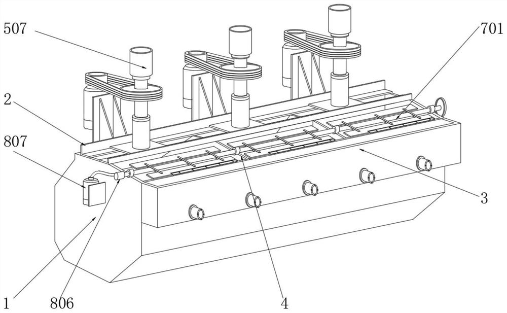
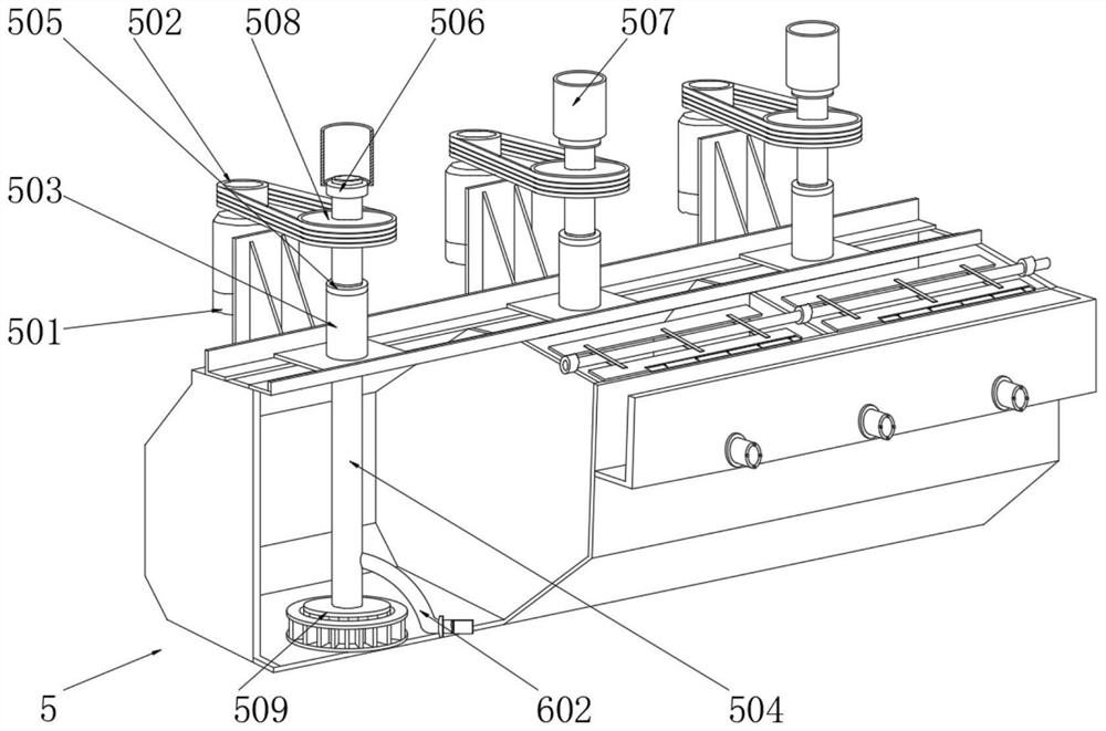
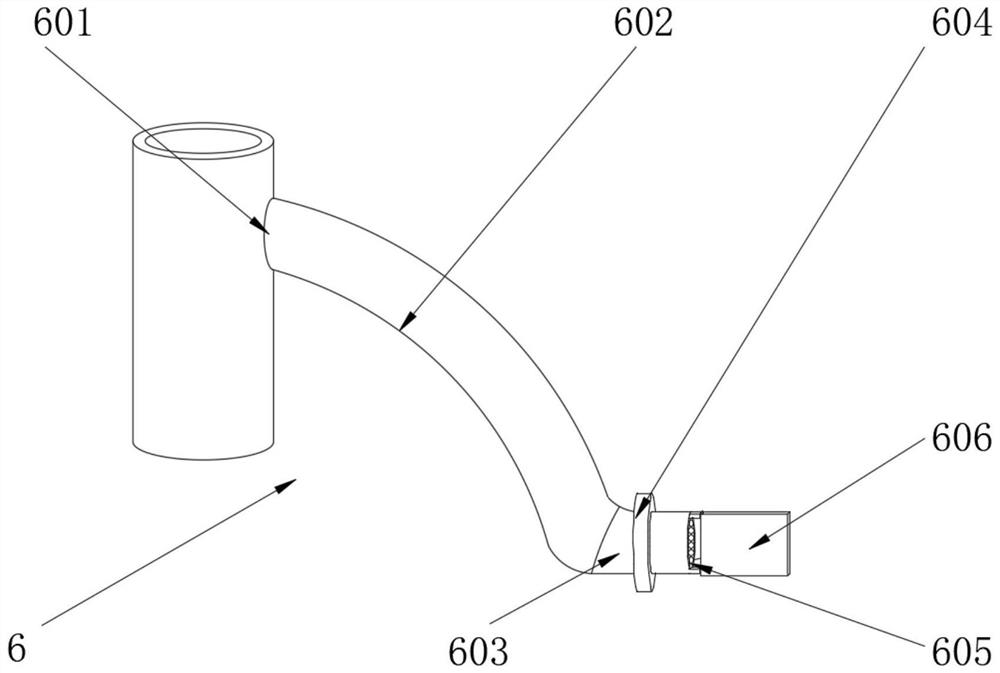
[0039] Example: such as Figure 1-6 As shown, the present invention provides a technical solution, a mechanical flotation machine, comprising a flotation cell 1, a mounting frame 2 is fixedly installed on the top of the flotation cell 1, and a selection tank 3 is fixedly installed on the top of the front of the flotation cell 1 , the inside of the flotation cell 1 is uniformly and fixedly equipped with partitions 4 .

[0040] The drive assembly 5 is installed on the top surface of the installation frame 2, and the drive assembly 5 includes a drive motor 501, a first pulley 502, a positioning pipe 503, a transmission pipe 504, a limit ring 505, a first bearing 506, a...


PUM


Abstract

The invention discloses a mechanical floatation machine. A driving assembly is installed on top surface of an installation frame; a positioning tube is fixedly arranged in the middle of the top surface of the installation frame; a first bearing is connected with a top end of a transmission tube in a sleeving manner; a anti-sedimentation assembly is arranged on one side of the transmission tube; an airing tube is fixedly connected with one side of a connection hole; a turning ring is connected with a middle part of a blowing tube in a sleeving manner; a bubble-scraping assembly is arranged on a top end of a baffle plate; a sand control assembly is arranged in the middle of a scraping plate shaft; a water storage groove is formed in a top end in a axle seat; a water feeding tube is connected with an outer side of a second bearing in a sleeving manner. Through the transmission tube, a large amount of air is directly transmitted into a rotor, the airing amount is increased; the transmission tube drives the airing tube to rotate; bubbles are produced during stirring of precipitates; mineral particles in the precipitates are combined with the bubbles; water is injected through a water pump, and injected out through a gap between the axle seat and the scraping plate shaft; solid particles between the axle seat and the scraping plate shaft are washed away; a water film is formed between the axle seat and the scraping plate shaft; thus, the lubricating effect is improved.

Description

technical field [0001] The invention relates to the technical field of flotation machines, in particular to a mechanical flotation machine. Background technique [0002] Flotation machine is a kind of mechanical equipment used to complete the flotation process. By stirring and aerating, some of the ore particles are selectively fixed on the air bubbles, float to the surface of the pulp and are scraped off to form foam products, so as to separate minerals. It is mainly used for sorting copper, zinc, lead, nickel, gold and other non-ferrous metals, and can also be used for rough selection and selection of ferrous metals and non-metals. [0003] However, during the use of the flotation machine, there is a small amount of aeration, and the ore particles are deposited on the bottom of the flotation tank, covered by the ore pulp, and cannot be fixed on the air bubbles. The inside of the ore pulp and foam contains more sediment and metal particles. The gap between the plate shaft ...

Claims


Application Information

Patent Timeline
Patent Type & Authority Patents(China)
IPC IPC(8): B03D1/02B03D1/16
CPCB03D1/02B03D1/1462B03D1/16
Inventor 周启明符晓东
Owner HUNAN SHIZHUYUAN NON FERROUS METAL
Learn More