
H-shaped steel column welding workstation

A technology for welding workstations and H-shaped steel, applied in welding equipment, auxiliary welding equipment, welding/cutting auxiliary equipment, etc., can solve the problems of welding, labor-intensive, and inability to clamp H-shaped steel columns of different sizes, and achieve clamping and High moving efficiency, improved welding efficiency, and shortened distance

Pending Publication Date: 2019-09-27
无锡金红鹰工业自动化有限公司
View PDF1 Cites 6 Cited by
  • Summary
  • Abstract
  • Description
  • Claims
  • Application Information

AI Technical Summary

Problems solved by technology

[0003] However, this welding method can only weld H-shaped steel columns of the same size, and cannot clamp and weld H-shaped steel columns of different sizes, and in the prior art, loading and unloading are carried out by manual handling It is impossible to grasp and move the workpiece in all directions and turn over the whole posture during welding to form a good welding posture and achieve the ideal welding effect. Moreover, this handling method is more labor-intensive, which makes the steel structure less effective during welding. Specifically, it provides a welding workstation for H-shaped steel columns, which can adapt to H-shaped steel columns of different sizes, realize the cycle loading and unloading of H-shaped steel columns, and improve the welding efficiency of steel structures

Method used


Image

  • H-shaped steel column welding workstation
  • H-shaped steel column welding workstation
  • H-shaped steel column welding workstation

Examples


Embodiment Construction

[0036]The following will clearly and completely describe the technical solutions in the embodiments of the present invention with reference to the accompanying drawings in the embodiments of the present invention. Obviously, the described embodiments are only some, not all, embodiments of the present invention. Based on the embodiments of the present invention, all other embodiments obtained by persons of ordinary skill in the art without creative efforts fall within the protection scope of the present invention.

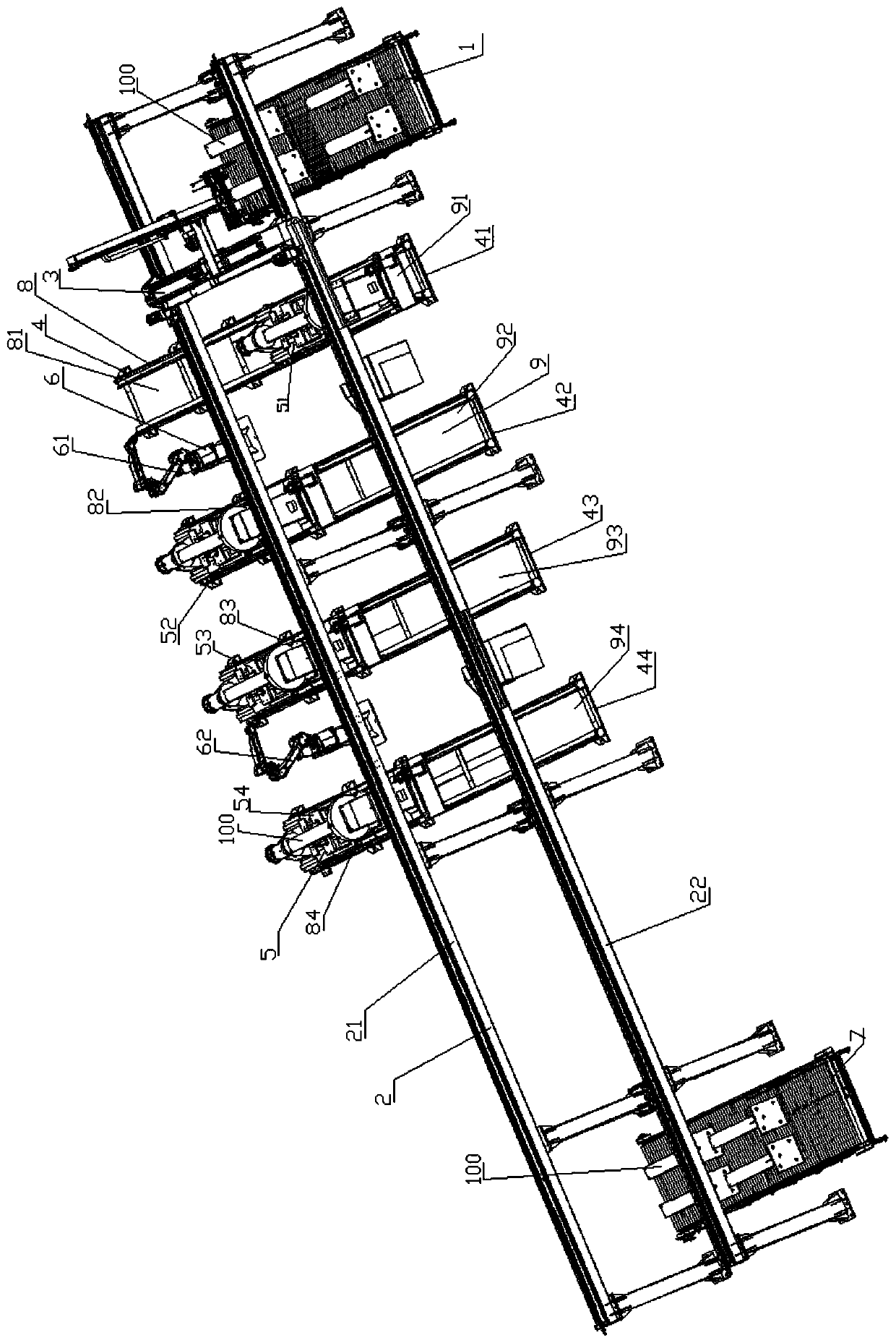
[0037] like figure 1 As shown, the technical solution of the present invention is achieved in that a kind of H-shaped steel column welding workstation comprises:

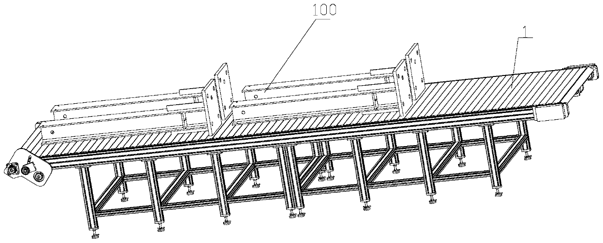
[0038] The first conveying device 1 is used to convey the H-shaped steel column 100 after the pretreatment is completed;

[0039] The truss 2 is erected above the first conveying device 1;

[0040] The transfer device 3 is slidably arranged on the bottom of the truss 2, and is used for grabbing and tran...


PUM


Abstract

The invention provides an H-shaped steel column welding workstation which comprises a first conveying device, a truss, a transferring device, a supporting device, a positioning device, a welding device and a second conveying device. The first conveying device is used for conveying pre-treated H-shaped steel columns; the truss is arranged above the first conveying device; the transferring device is slidably arranged at the bottom of the truss; the supporting device is arranged on the left side of the first conveying device; the positioning device is arranged on the upper surface of the supporting device; the welding device is arranged in the supporting device for welding the H-shaped steel columns clamped and moved by the positioning device; the second conveying device is arranged on the left side of the supporting device; the left end of the truss is arranged on the left side of the second conveying device, the right end of the truss is arranged at the right end of the first conveying device, the front side of the truss is arranged above the first conveying device, and the back side of the truss is arranged in the middle of the upper side of the positioning device. Therefore, the H-shaped steel column welding workstation has the advantages of being suitable for H-shaped steel columns of different dimensions, loading and unloading the H-shaped steel columns circularly and enhancing the welding efficiency of the H-shaped steel columns.

Description

technical field [0001] The invention belongs to the field of welding workstations, in particular to an H-shaped steel column welding workstation. Background technique [0002] At present, the structure is made of steel plates and hot-rolled, cold-formed or welded profiles (I-beams, profiled steels, profiled steel plates, H-shaped steels, etc.) through connectors (bolts, high-strength bolts, etc.) The structural form; the steel structure has the characteristics of light weight, high strength, good seismic performance, energy saving and land saving, recyclable utilization, short construction period, and less environmental pollution during construction and dismantling, so the scope of use of steel structures is wider. It is more and more extensive, so the requirements for steel structure welding are also getting higher and higher. Chinese patent CN205914953U discloses an H-shaped steel splicing device for a steel structure production line, which can uniformly weld the seams and...

Claims


Application Information

Patent Timeline
Patent Type & Authority Applications(China)
IPC IPC(8): B23K37/00B23K37/047
CPCB23K37/00B23K37/047
Inventor 冯华兴秦晓东高晓杰
Owner 无锡金红鹰工业自动化有限公司
Learn More