Electric automobile regenerative braking force distribution method integrating road surface identification

A technology for regenerative braking force and electric vehicles, which is applied in the direction of electric vehicles, electric braking systems, control devices, etc., can solve the problems that electric vehicles have not been widely popularized, the braking efficiency is poor, and the road adhesion coefficient is not considered. Improve energy recovery efficiency, quick response, and good braking performance

Active Publication Date: 2019-09-27
NANJING UNIV OF AERONAUTICS & ASTRONAUTICS
View PDF3 Cites 14 Cited by
  • Summary
  • Abstract
  • Description
  • Claims
  • Application Information

AI Technical Summary

Problems solved by technology

Although electric vehicles have their incomparable advantages, the development of electric vehicles has not been widely popularized for the time being. The reason is that electric vehicles also have their fatal shortcomings: the problem of driving range
The first two improvement strategies do not consider the influence of road surface adhesion coefficient, and the braking efficiency is poor, while the third allocation strategy that integrates road surface recognition, in the existing technology, the road surface is classified into three types: high, medium and low. , although this strategy takes into account the influence of road surface adhesion coefficient, the consideration is relatively simple

Method used


Image

  • Electric automobile regenerative braking force distribution method integrating road surface identification
  • Electric automobile regenerative braking force distribution method integrating road surface identification
  • Electric automobile regenerative braking force distribution method integrating road surface identification

Examples


Embodiment Construction

[0041] The present invention is described in detail below in conjunction with accompanying drawing and specific embodiment:

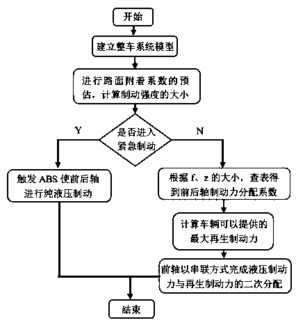
[0042] like figure 1 Shown is a flow chart of the braking force distribution strategy of the vehicle during the braking process. When the vehicle is in emergency braking, the ABS device is triggered to perform pure hydraulic braking. When the vehicle is in a non-emergency braking state, according to the distribution method of the present invention Assignment involves the following steps:

[0043] Step 1: Establish the vehicle model of the vehicle, including tire model, vehicle dynamics model, motor model, battery model and braking system model. Table 1 shows some structural parameters of this embodiment, and the vehicle is a front-drive pure electric car;

[0044] Table 1

[0045]

[0046] Step 2: Obtain the three easily obtained state parameters of longitudinal acceleration, lateral acceleration and front wheel angle through the sensor, and estim...


PUM


Abstract

The invention discloses an electric automobile regenerative braking force distribution method integrating road surface identification, and belongs to the field of electric automobile energy recovery. The method can ensure that a vehicle has good braking efficiency and obviously improves the energy recovery efficiency of the vehicle. The electric automobile regenerative braking force distribution method integrating road surface identification comprises the following steps: firstly, determining structural parameters of a whole automobile by establishing a vehicle model; obtaining three easily-obtained state information of a vehicle, like current longitudinal acceleration, lateral acceleration and front wheel rotation angle through a sensor, and obtaining a current road surface adhesion coefficient based on extended Kalman filtering estimation; then obtaining the current braking strength of the vehicle through calculation by a main cylinder pressure sensor, and judging whether the vehicle is in an emergency braking state or not; and if the vehicle is in a non-emergency state, under the premise of ensuring the driving safety of the vehicle, obtaining a front axle and rear axle braking force distribution coefficient based on table looking up of the magnitude of the road surface adhesion road surface and the braking strength, and then distributing the hydraulic braking force and the regenerative braking force by the front axle total braking force in a serial distribution mode.

Description

technical field [0001] The invention belongs to the field of energy recovery of electric vehicles, and in particular relates to a regenerative braking force distribution method of electric vehicles integrated with road surface recognition. Background technique [0002] With the rapid development of the automobile industry, while traditional fuel vehicles bring people a lot of convenience, they also bring enormous pressure to the environment and resources. However, pure electric vehicles use electric energy as the driving energy, without oil consumption and combustion. Therefore, the development of pure electric vehicles will alleviate environmental problems and energy problems to a certain extent. Although electric vehicles have their incomparable advantages, the development of electric vehicles has not been widely popularized for the time being. The reason is that electric vehicles also have their fatal shortcomings: the problem of driving range. However, studies have foun...

Claims


Application Information

Patent Timeline
Patent Type & Authority Applications(China)
IPC IPC(8): B60W50/00B60W40/06B60W40/107B60W40/109B60W40/10B60L7/10
CPCB60L7/10B60W40/06B60W40/10B60W40/107B60W40/109B60W50/00B60W2050/0031B60W2050/0037
Inventor 周健豪孙静赵万忠宋廷伦丁一何龙强
Owner NANJING UNIV OF AERONAUTICS & ASTRONAUTICS
Why Eureka
Try Eureka