
Cementing equipment with mutually standby hydraulic systems

A hydraulic system and cementing technology, which is applied to mechanical equipment, wellbore/well components, non-variable-capacity pumps, etc., can solve the problem of inability to achieve complete backup of dual-pump cementing equipment, hydraulic systems that are not mutually backup, and waste of manpower resources and other issues, to achieve the effect of reducing customer operating costs, improving equipment reliability, and improving equipment operation safety

Pending Publication Date: 2019-09-27
YANTAI JEREH PETROLEUM EQUIP & TECH CO LTD
View PDF0 Cites 108 Cited by
  • Summary
  • Abstract
  • Description
  • Claims
  • Application Information

AI Technical Summary

Problems solved by technology

However, this method cannot realize the complete backup of the double-pump cementing equipment, so the general cementing operation requires two cementing equipment, one for use and the other for standby, the operation cost is relatively high, and human resources are wasted
[0003] The current conventional double-pump cementing equipment is diverse, such as 2 sets of power units + 2 plunger pumps + 2 clean water centrifugal pumps + 2 mud centrifugal pumps, the A-side engine hydraulic system drives 1 clean water centrifugal pump and 1 mud centrifugal pump, the engine hydraulic system on side B drives another clean water centrifugal pump and another mud centrifugal pump respectively; the hydraulic systems are not mutually backup, when the engine on side A is damaged, any centrifugal pump on side B will When damaged, the equipment cannot work; similarly, when the engine on side B is damaged and any one of the centrifugal pumps on side A is damaged, the equipment cannot work either

Method used


Image

  • Cementing equipment with mutually standby hydraulic systems
  • Cementing equipment with mutually standby hydraulic systems

Examples


Embodiment Construction

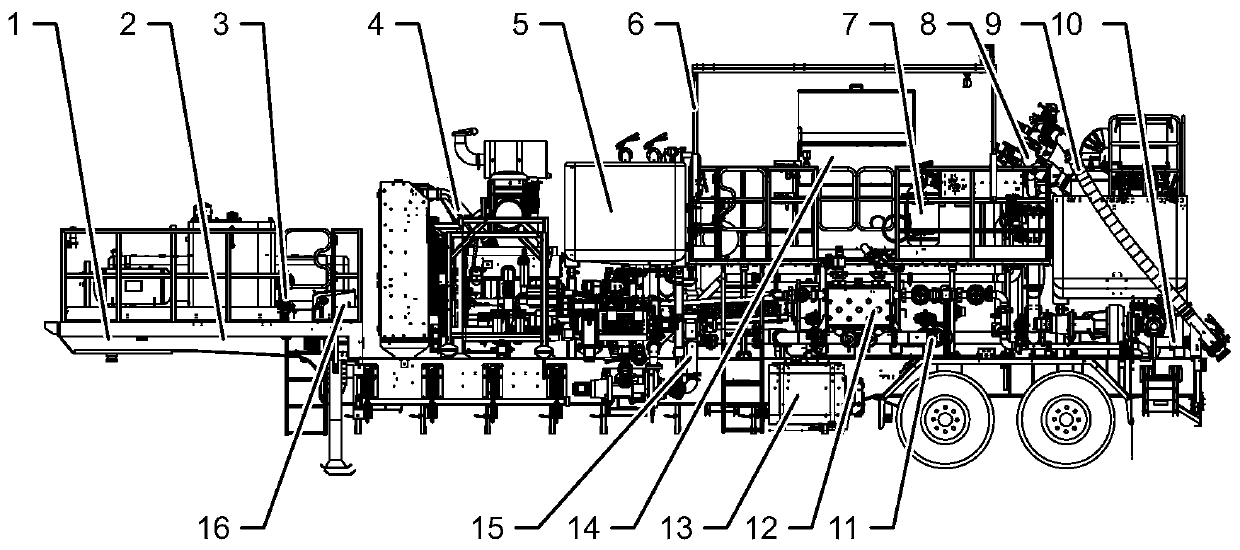
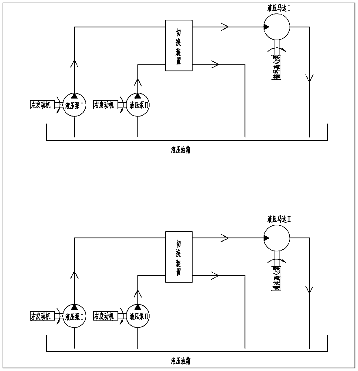
[0026] The present invention will now be further described in detail in conjunction with the accompanying drawings and embodiments. These drawings are all simplified schematic diagrams, only illustrating the basic structure of the present invention in a schematic manner, so it only shows the composition related to the present invention.

[0027] It should be noted that when an element is referred to as being "fixed to" another element, it may be directly on the other element or an intervening element may also exist. When a component is said to be "connected" to another component, it may be directly connected to the other component or intervening components may also be present. As used herein, the terms "upper", "lower", "inner", "outer", "left", "right" and similar expressions are for the purpose of illustration only and do not represent the only embodiment.

[0028] Such as figure 1 , figure 2 As shown, a cementing equipment in which the hydraulic system is a backup for ea...


PUM


Abstract

The invention discloses cementing equipment with mutually standby hydraulic systems. The cementing equipment comprises a loading system, a hydraulic system connected with the loading system and a power system for driving the hydraulic system. The hydraulic system at least comprises a hydraulic pump, a switching device and an overflow valve, the hydraulic system is connected with a mixing system, and the hydraulic system is connected with a slurry mixing system provided with an AMS automatic slurry mixing system, a centrifugal pump circulating and filling system; the slurry mixing system is controlled and adjusted through a control system, the control system is arranged on a computer control platform, and the control platform is arranged on the loading system; and the loading system is based on one or more of a vehicle-mounted chassis or a trailer chassis or a skid-mounted chassis, wherein a semi-trailer based on the trailer chassis can be fixedly connected with a plurality of engines, a plurality of gear boxes, a plurality of plunger pumps, at least one metering tank, the slurry mixing system, a high-low pressure manifold, the control system, the hydraulic system and an electrical system.

Description

technical field [0001] The invention relates to the field of petroleum equipment, in particular to a cementing equipment in which hydraulic systems serve as backups for each other. Background technique [0002] As cementing equipment is more and more widely used in well site operations at home and abroad, the concept of cementing operation quality, personnel safety, equipment safety and operation safety is becoming more and more prominent, and customers put forward stricter requirements for equipment quality and equipment reliability. . Conventional cementing equipment is generally designed through the principle of low-pressure manifold to realize mutual backup of centrifugal pumps. However, this method cannot realize the complete backup of the double-pump cementing equipment, so the general cementing operation requires two cementing equipment, one for use and the other for standby, the operation cost is relatively high, and human resources are wasted. [0003] The current...

Claims


Application Information

Patent Timeline
IPC IPC(8): E21B33/13F02B63/06F04D13/02F04D13/14
CPCE21B33/13F02B63/06F04D13/02F04D13/14
Inventor 路君卫李明升刘士堂李恩杰刘仁王彦峰梁虎刘园刘永诚
Owner YANTAI JEREH PETROLEUM EQUIP & TECH CO LTD
Learn More