

Rapid constant temperature high definition dyeing structural unit and high definition dyeing method
Patent Information
- Authority / Receiving Office
- CN · China
- Patent Type
- Applications(China)
- Current Assignee / Owner
- ZHENGZHOU ZHONGPU MEDICAL INSTR CO LTD
- Publication Date
- 2019-09-27
Smart Images
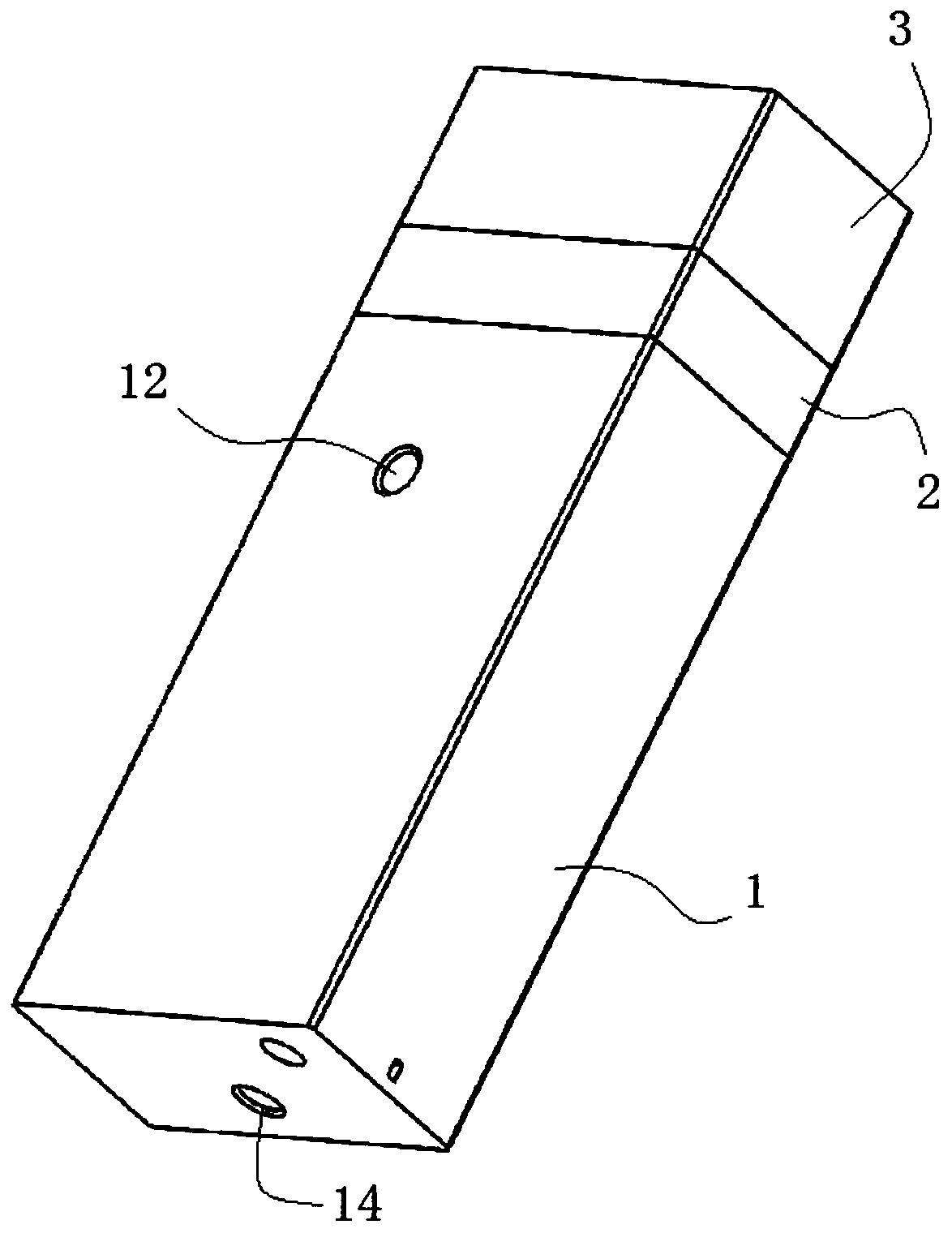
Figure 1 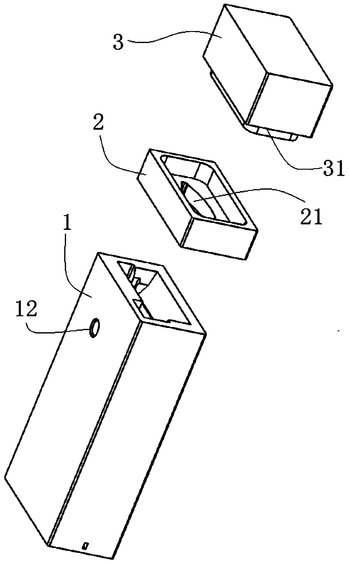
Figure 2 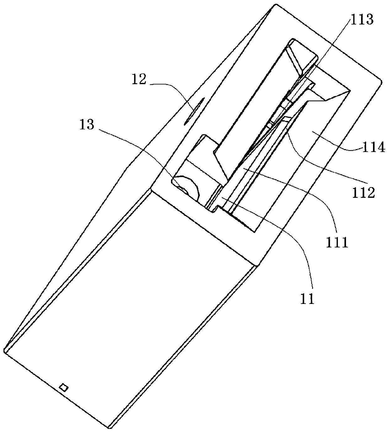
Figure 3
Abstract
Description
technical field
[0001] The invention relates to the field of biochemical dyeing, in particular to a rapid constant temperature high-definition dyeing structural unit and a high-definition dyeing method. Background technique
[0002] In the fields of hematological staining, microbiological staining, pathological staining, cytological staining, reproductive medicine staining, and nuclear chromosome staining, artificial staining or instrumental staining is usually used, but there are the following problems:
[0003] In existing manual dyeing methods, different people will produce large artificial differences in results, and some dyeing operations have many steps and take up a lot of time and labor.
[0004] The staining effect of the existing automatic staining instrument is not good or the reagent consumption is relatively large. Most of the staining instruments are centrifugal staining, it is troublesome to load or take the slides, and it is necessary to distinguish the fron...