
Finite element calculation method for nonlinear gas-solid coupling heat exchange problem

A technology of coupling heat transfer and calculation method, which is applied in the fields of aero-engine design, heat transfer, and finite element method, and can solve the problems of reducing cooling efficiency, restricting the design level of aero-engine, and not considering the coupled heat transfer effect of gas-solid boundary.

Active Publication Date: 2019-09-27
SHANGHAI JIAO TONG UNIV
View PDF4 Cites 3 Cited by
  • Summary
  • Abstract
  • Description
  • Claims
  • Application Information

AI Technical Summary

Problems solved by technology

This traditional heat transfer analysis method does not consider the coupling heat transfer effect of the gas-solid boundary, which will cause large calculation errors under high temperature conditions, and cannot accurately calculate the temperature field of parts such as turbines, which restricts the design level of my country's aero-engines
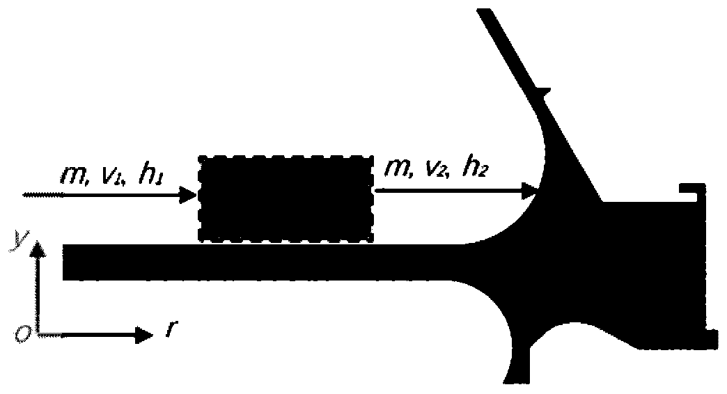
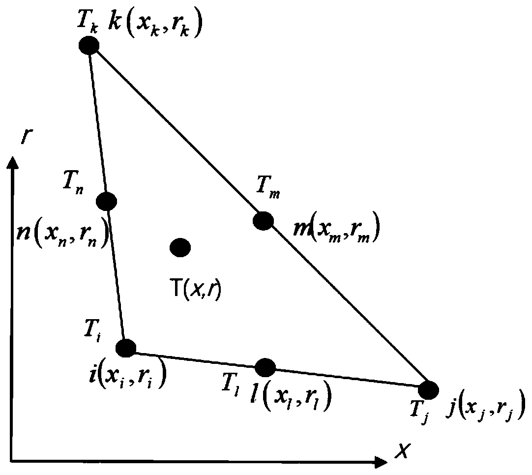
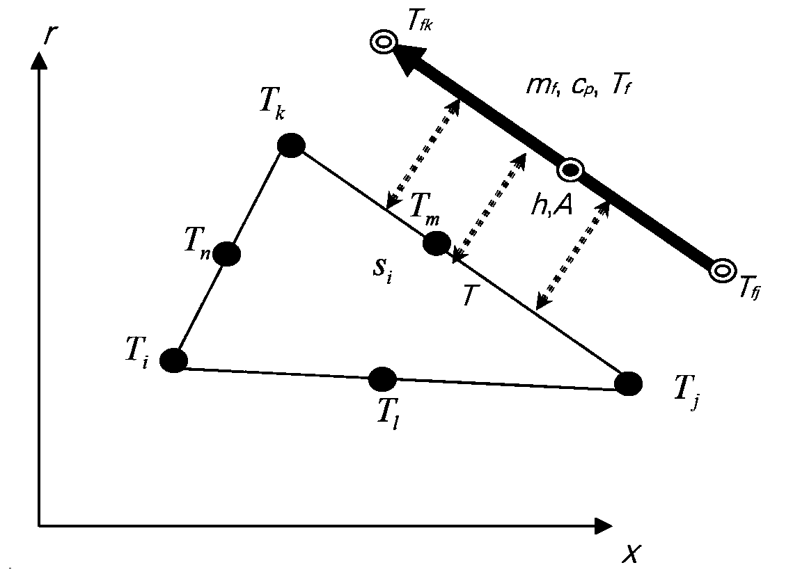
[0021] Therefore, those skilled in the art are committed to developing a finite element calculation method for nonlinear gas-solid coupling heat transfer problems, aiming at the flow of cooling gas in aeroengine design In the process, due to heat absorption, the temperature rises, which in turn leads to the technical problem of a sharp decrease in the cooling efficiency of the gas to the solid (such as a turbine disk). Based on the principle of energy balance in the heat transfer process, a nonlinear six-node triangular element finite element model is established, and an effective numerical calculation method is proposed

Method used


Image

  • Finite element calculation method for nonlinear gas-solid coupling heat exchange problem
  • Finite element calculation method for nonlinear gas-solid coupling heat exchange problem
  • Finite element calculation method for nonlinear gas-solid coupling heat exchange problem

Examples


Embodiment Construction

[0088] The following describes the preferred embodiments of the present invention with reference to the accompanying drawings to make the technical content clearer and easier to understand. The present invention can be embodied in many different forms of embodiments, and the protection scope of the present invention is not limited to the embodiments mentioned herein.

[0089] The invention includes a gas-solid coupling convective heat transfer model of axisymmetric components, a gas temperature rise model of a six-node triangular boundary unit, an overall finite element model, an implementation plan of an aeroengine gas-solid coupling heat transfer analysis technology, and the like.

[0090] (1) Energy balance model in convective heat transfer

[0091] In order to accurately calculate the cooling (or heating) effect of the gas (fluid) on the solid, the present invention takes the gas boundary temperature T f Calculated as a physical variable. The present invention abandons t...


PUM


Abstract

The invention discloses a finite element calculation method for a nonlinear gas-solid coupling heat exchange problem, and relates to the technical field of heat transfer science, finite element methods and aero-engine design. The method comprises the following steps of reading an axisymmetric part three-dimensional geometric model file established by a CAD system, and carrying out detail feature processing; selecting and intercepting an axisymmetric meridian plane to obtain a two-dimensional geometric model; dividing the meridian plane into the triangular unit grids; establishing a finite element model of the internal triangular unit and the boundary unit; superposing and synthesizing an integral finite element model of the axisymmetric region to obtain a linear algebraic equation set about all node temperatures; and solving the linear algebraic equation set, obtaining a numerical value of the node temperature, and carrying out computer graphic visualization display. According to the method, the defects of a classic heat transfer analysis method are overcome, the coupling effect of the gas-solid heat exchange is fully considered, compared with a linear gas-solid heat coupling algorithm, the temperature field distribution of an aero-engine part structure can be more accurately calculated, and the design level is improved.

Description

technical field [0001] The invention relates to the technical fields of heat transfer, finite element method and aeroengine design, in particular to a finite element calculation method for a nonlinear gas-solid coupled heat transfer problem. Background technique [0002] The development of aero-engines is of great significance to national economic construction and national defense construction, and reflects a country's technical level and industrial capabilities. There is still a large gap between my country's aero-engine development level and the world's advanced level. Breaking through foreign technology monopoly and innovatively developing high-performance aero-engines have become arduous tasks for the scientific and industrial circles. [0003] At present, my country is developing high-performance military aeroengines. In order to increase the thrust, the temperature of the gas in front of the turbine needs to be greatly increased, and at the same time, the structural we...

Claims


Application Information

Patent Timeline
IPC IPC(8): G06F17/50
CPCG06F30/15G06F2119/08G06F30/23
Inventor 王成恩
Owner SHANGHAI JIAO TONG UNIV
Learn More