Kinematics forecast compensation mechanism-based surrounding vehicle behavior real-time identification method

A technology of compensation mechanism and identification method, which is applied in the direction of road vehicle traffic control system, traffic control system, special data processing application, etc., can solve the problem of incomplete historical information, little practical significance of intelligent vehicles, lack of real-time recognition and application To achieve the effect of enhancing applicability and accuracy, shortening the calculation time of probability estimation, and enhancing the real-time performance of recognition

Active Publication Date: 2019-09-27
JIANGSU UNIV
View PDF10 Cites 8 Cited by
  • Summary
  • Abstract
  • Description
  • Claims
  • Application Information

AI Technical Summary

Problems solved by technology

The existing hot spot feature conversion method only uses the historical location information of surrounding vehicles, and the recognition is often completed after the behavior has been basically completed. At this time, the recognition result has little practical significance for intelligent vehicles, and lacks real-time recognition and applicability.
In addition, in the initial stage of the execution of a certain surrounding vehicle behavior, the recognition accuracy is generally low due to the incomplete historical information of the behavior in the observation sequence and the interference of the previous vehicle behavior information.

Method used


Image

  • Kinematics forecast compensation mechanism-based surrounding vehicle behavior real-time identification method
  • Kinematics forecast compensation mechanism-based surrounding vehicle behavior real-time identification method
  • Kinematics forecast compensation mechanism-based surrounding vehicle behavior real-time identification method

Examples


Embodiment Construction

[0039] The present invention will be further described below in conjunction with drawings and embodiments.

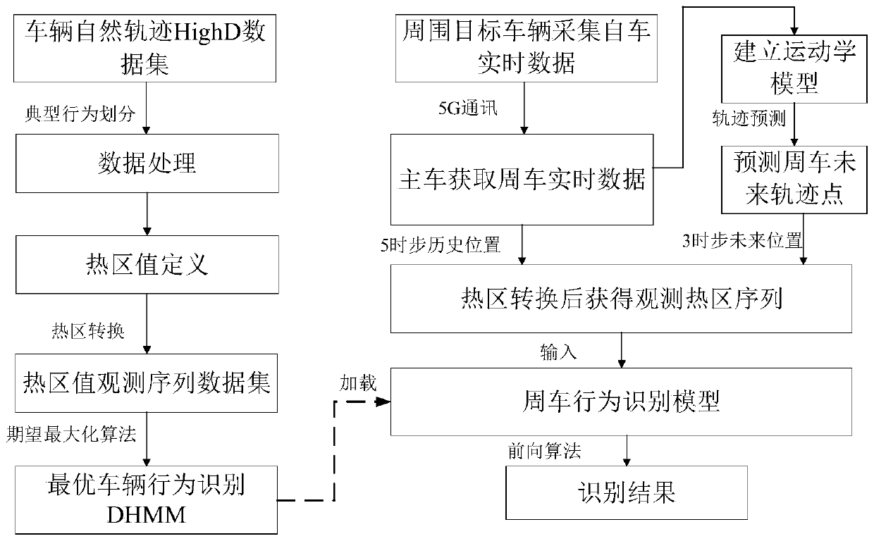
[0040] Such as figure 1 Shown, implementation of the present invention comprises as follows:

[0041] Step1: The typical behavior of Zhouche and the definition of hot zone

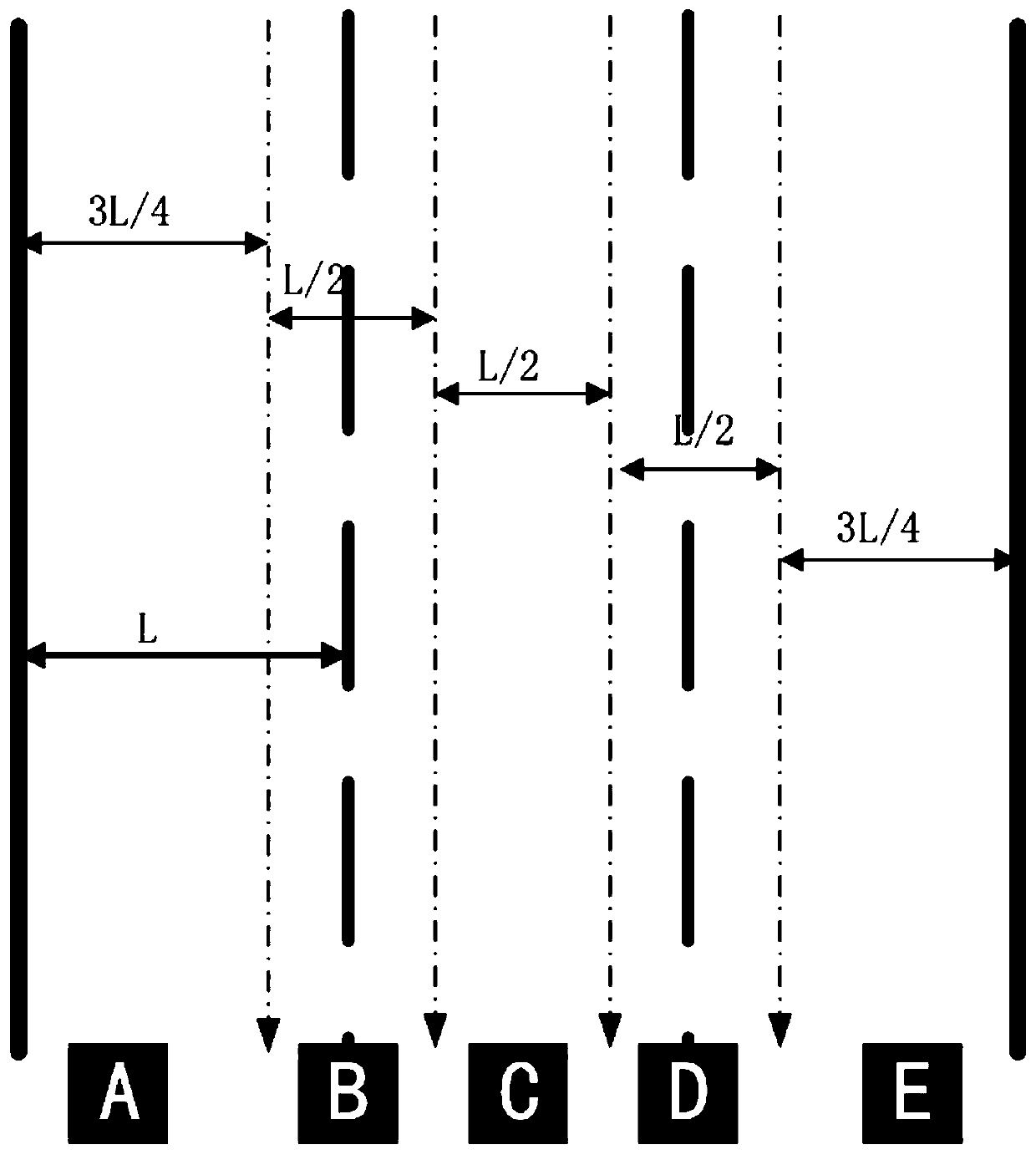
[0042] The typical behaviors of surrounding vehicles are classified into maneuvers, which are left lane change, right lane change, and lane keeping. For vehicles, my country's expressway is a two-way three-lane type. Taking this as an example, the road is divided into five hot spots in combination with the lane line and the shoulder position, and each area has a corresponding hot spot value, which is A, B, C, D, E. Among them, let the lane width be L. Let the area A be between the left shoulder and L / 4 on the right side of the centerline of the left lane, and area B between the L / 4 on the right side of the centerline of the left lane and L / 4 on the left side of the centerline of the middle lane. ...


PUM


Abstract

The invention discloses a kinematics forecast compensation mechanism-based surrounding vehicle behavior real-time identification method. The kinematics forecast compensation mechanism-based surrounding vehicle behavior real-time identification method comprises the steps of defining surrounding vehicle typical behavior and a hot region, in which maneuvering behavior classification is performed on the surrounding vehicle typical behavior, and a road is divided into five hot spot regions by combining a lane line and a road shoulder position; performing off-line training on a hidden Markov vehicle behavior identification model, in which a discrete hidden Markov model (DHMM) is built for each maneuvering classification, and each DHMM is trained by an EM algorithm to obtain most excellent DHMM group; building a vehicle track forecast kinematic model, in which track can be forecasted by the vehicle track forecast kinematic model, and position sequence information of the vehicle in future three time steps are generated; and performing on-line and real-time identification, in which the acquired vehicle historical five-time step position sequence and the forecasted vehicle future three-time step position sequence are converted to eight-time step hot region sequence and are input to the trained hidden Markov vehicle behavior identification model, and forward calculation and identification is performed to obtain the behavior of the surrounding target vehicle.

Description

technical field [0001] The invention belongs to the technical field of intelligent driving, and in particular relates to a method for real-time recognition of surrounding vehicle behavior based on a kinematics prediction and compensation mechanism. Background technique [0002] Nowadays, whether it is advanced driver assistance systems or fully autonomous vehicles, scholars in various fields have aroused extensive research interests. There is no doubt that automotive intelligence has become one of the most important trends and trends in the development of the automotive industry. In addition, the 5G communication era is coming, and our country is one of the leaders leading this era. The V2X communication of 5G Internet of Vehicles based on D2D technology has an air interface delay of about 1ms and an end-to-end delay of milliseconds. Accurately obtain the status information of surrounding vehicles in real time under the scene. At this stage, the biggest challenge for us to...

Claims


Application Information

Patent Timeline
Patent Type & Authority Applications(China)
IPC IPC(8): G08G1/017G06F17/50
CPCG08G1/017G06F30/20
Inventor 蔡英凤邰康盛王海陈小波李祎承刘擎超
Owner JIANGSU UNIV
Why Eureka
Try Eureka