Detector array target calibration system and method

A detector array and calibration system technology, applied in the field of detector array target calibration, can solve the problems of high cost, high difficulty and low efficiency, etc.

Active Publication Date: 2019-10-01
HEFEI INSTITUTES OF PHYSICAL SCIENCE - CHINESE ACAD OF SCI
View PDF2 Cites 6 Cited by
  • Summary
  • Abstract
  • Description
  • Claims
  • Application Information

AI Technical Summary

Problems solved by technology

At present, there are problems such as difficulty, high cost, an

Method used


Image

  • Detector array target calibration system and method
  • Detector array target calibration system and method
  • Detector array target calibration system and method

Examples


Embodiment 1

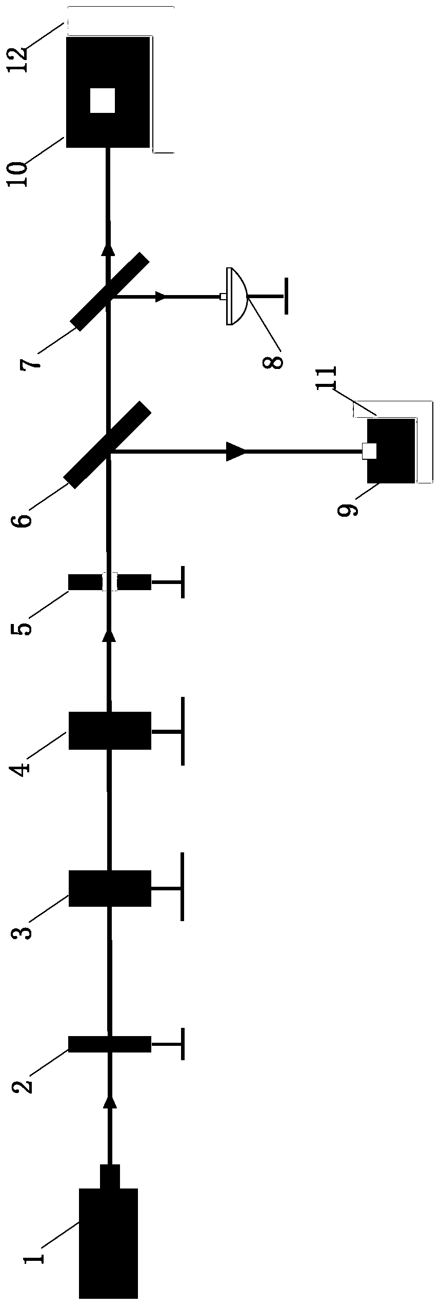
[0033] Such as figure 1 and Figure 7 As shown, a detector array target calibration system includes a spot acquisition device, a first beamsplitter 6, a second beamsplitter 7, a power meter 8, a signal conditioning sampling unit, a data processing control unit, and a distance to the first beamsplitter 6. The same calibration detector module 9 and detector array target 10 to be calibrated. In this embodiment, the calibration detector module 9 has only one detector unit 101 , and the detector array target 10 includes a plurality of detector units 101 arranged in an array. The light spot 13 output by the described light spot acquisition device is respectively emitted to the calibration detector module 9 and the detector array target 10 to be calibrated after passing through the first beam splitter 6, and the second beam splitter 7 arranged on the optical path splits a beam The light is emitted onto the power meter 8; in this embodiment, the second beam splitter 9 is arranged on...

Embodiment 2

[0050] A method for using a detector array target calibration system described in Embodiment 1, comprising the following steps:

[0051] S1. Build a system, match a suitable spot acquisition device according to the measurement wavelength and power density range of the detector array target 10 to be calibrated, and then build the system;

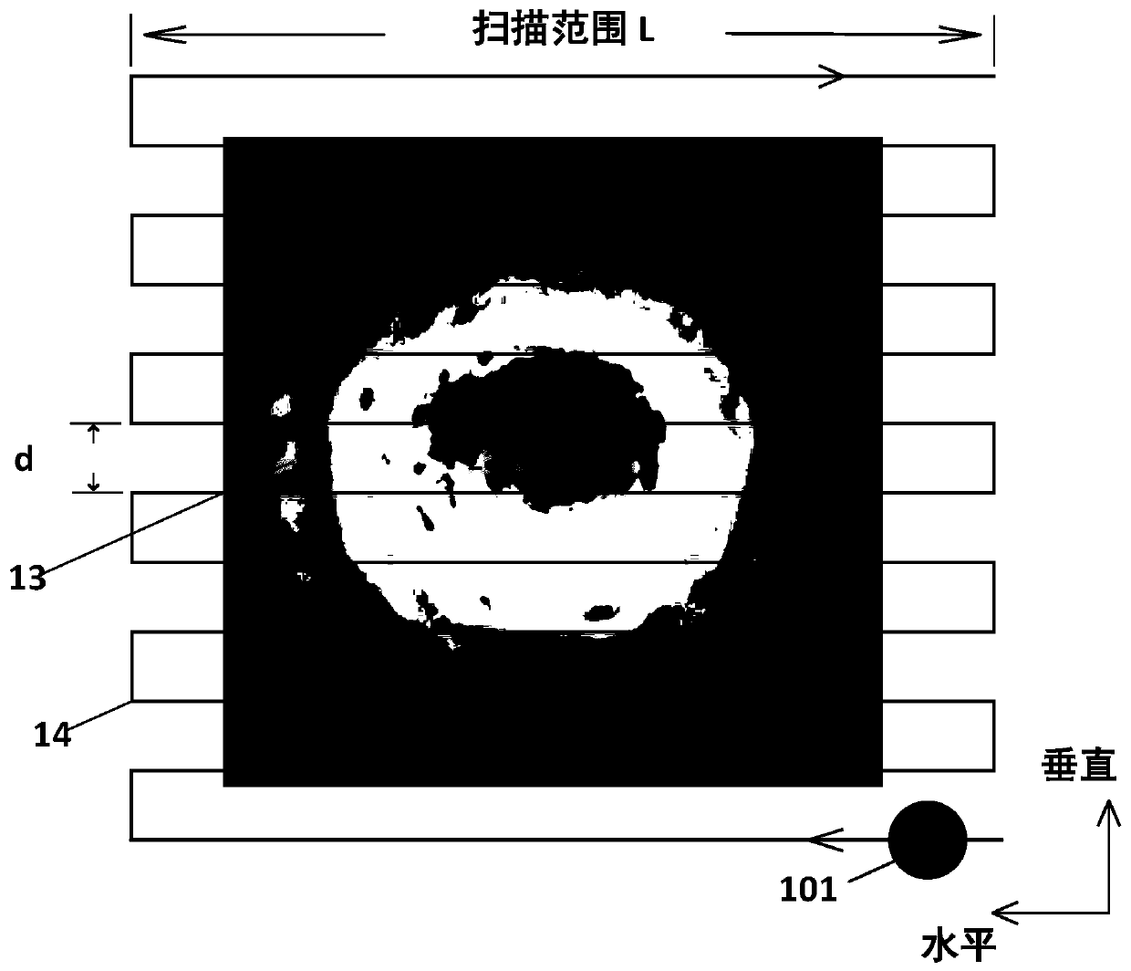
[0052] S2. The data processing control unit controls the first two-dimensional scanning platform 11 to drive the standard calibration detector module 9 to perform single-point scanning according to the set path 14 . After the scan is completed, the signal conditioning sampling unit collects the AD response value of the detector unit 101 in the standard calibration detector module 9, and then transmits it to the data processing control unit, and the data processing control unit obtains the light spot 13 counted by the power meter 8 Total power P sum , to calculate the true power density ρ;

[0053] The specific steps are as follows:

[0054...


PUM


Abstract

The invention relates to a detector array target calibration system and method. The system comprises a light spot acquisition device, a first spectroscope, a second spectroscope, a power meter, a calibration detector module, and a to-be-calibrated detector array target, wherein the calibration detector module and the to-be-calibrated detector array target are in the same distance to the first spectroscope; light spots output by the light spot acquisition device are transmitted to the calibration detector module and the detector array target respectively after passing through the first spectroscope, the second spectroscope arranged on an optical path is used for emitting a beam of light to the power meter; and a first two-dimensional scanning platform and a second two-dimensional scanning platform enable the corresponding calibration detector module and the detector array target to perform full-coverage scanning of a set path on a plane directly facing the light spots. According to thesystem in the invention, the calibration detector module is matched with the power meter so as to obtain the real power density of a calibration light source output by the light spot acquisition device, and the two-dimensional scanning platforms are arranged, so that the straightness and running precision during full-coverage scanning of the calibration detector module and the detector array target on the set path are ensured.

Description

technical field [0001] The invention relates to the technical field of detector array target calibration, in particular to a detector array target calibration system and method. Background technique [0002] In order to quantitatively analyze the performance parameters of the laser emission system, it is necessary to measure the space-time distribution of the absolute power density of the laser spot to obtain various parameters such as the total power of the laser spot, the size of the spot, and the space-time distribution of the power density, and provide a basis for comprehensively judging the beam quality. The detector array target to be calibrated is a special measuring device used to measure the spatio-temporal distribution of laser beam power density and total power and other parameters. The detector array target to be calibrated generally consists of tens to thousands of detector unit channels. The detector array target to be calibrated converts the spot intensity in...

Claims


Application Information

Patent Timeline
IPC IPC(8): G01J1/00
CPCG01J1/00
Inventor 谭逢富何枫靖旭陈修涛黄志刚侯再红乔春红
Owner HEFEI INSTITUTES OF PHYSICAL SCIENCE - CHINESE ACAD OF SCI
Why Eureka
Try Eureka