Supercharge Your Innovation With Domain-Expert AI Agents!

Buffer distribution structure of chromatographic column

A chromatography column and distribution plate technology, which is applied in the field of buffer distribution structure, can solve problems such as uneven use of resin, uneven entry of resin, poor chromatography effect, etc.

Pending Publication Date: 2019-10-08
JIANGSU HAGONG PHARMA MACHINE TECH CO LTD
View PDF0 Cites 0 Cited by
  • Summary
  • Abstract
  • Description
  • Claims
  • Application Information

AI Technical Summary

Problems solved by technology

In the process of extraction and separation, a chromatographic column is needed. The principle of the distributor in the traditional chromatographic process is similar to the principle of the shower we use every day. However, due to the unstable flow rate of the pipeline at the top of the chromatographic column, the distributor will distribute to Inhomogeneity of the liquid in the chromatography column
When the liquid output from the top pipe is large, the local flow rate is too large, so that when the liquid enters the resin in the chromatography column, the flow rate in some areas is too large, resulting in uneven chromatography
When the output volume of the top pipe is small, the distributor does not have enough volume to distribute, which will also cause uneven resin entry, resulting in poor chromatography
And when the liquid is distributed from the distributor into the chromatography column, it flows directly from the middle of the chromatography column, so that the use of the resin in the chromatography column is uneven, and the resin in the middle of the chromatography column is used frequently, while the surrounding resin is less. low usage

Method used


Image

  • Buffer distribution structure of chromatographic column
  • Buffer distribution structure of chromatographic column
  • Buffer distribution structure of chromatographic column

Examples


Embodiment Construction

[0021] The present invention will be described in further detail below through specific examples.

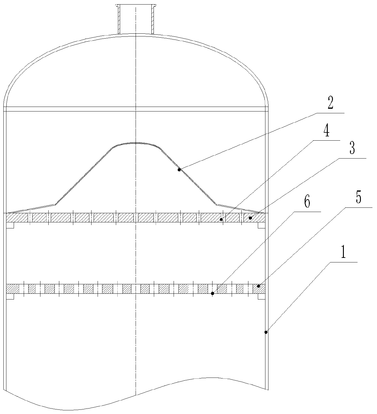
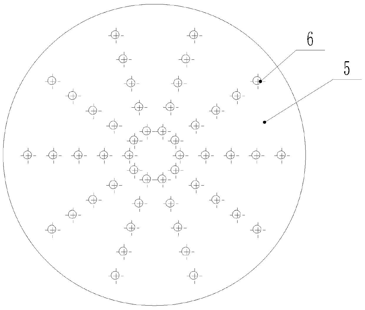
[0022] Such as Figure 1 to Figure 4 As shown, a buffer distribution structure of a chromatographic column 1 is installed on the upper end of the chromatographic column 1 and above the solid phase particles. The solid phase particles are generally resin particles, and the buffer distribution structure is arranged from top to bottom. It includes a buffer cap 2, a primary distribution plate 3 and a secondary distribution plate 5. The middle part of the buffer cap 2 is arched upwards, and the outer periphery of the buffer cap 2 is provided with leakage holes, and the primary distribution plate 3 is provided with several primary distribution plates. hole 4, the secondary distribution plate 5 is provided with several installation holes 6, the primary distribution plate 3 and the secondary distribution plate 5 are arranged at intervals to form a material liquid buffer zone, and the in...


PUM


Abstract

The invention discloses a buffer distribution structure of a chromatographic column. The buffer distribution structure is mounted at the upper end of the chromatographic column and located above solid-phase particles. The buffer distribution structure structurally comprises a buffer cap, a primary distribution plate and a secondary distribution plate from top to bottom and is characterized in thatthe middle of the buffer cap is upwardly arched, the periphery of the buffer cap is provided with liquid leakage holes, the primary distribution plate is provided with a plurality of primary distribution holes, the secondary distribution plate is provided with a plurality of mounting holes, the primary distribution and the secondary distribution plate are arranged at intervals to form a feed liquid buffer area, pressure-sensing flow discharge switches are detachably mounted on the mounting holes of the secondary distribution plate, and the pressure-sensing flow discharge switches are switchedon or off by sensing the pressure of the feed liquid buffer area. The buffer distribution structure can buffer liquid entering the chromatographic column and is uniform in distribution, and accordingly resin utilization rate of each part in the chromatographic column is identical.

Description

technical field [0001] The invention relates to a buffer distribution structure, in particular to a buffer distribution structure of a chromatographic column. Background technique [0002] Cannabidiol (CBD), a cannabinoid found in the cannabis plant, is gaining popularity as an alternative treatment for common ailments. Unlike tetrahydrocannabinol (THC), another cannabinoid found in the cannabis plant, CBD has no psychoactive effects. However, when CBD is ingested, only 20% is absorbed, which means that for CBD to be more effective, extraction and isolation of CBD must be performed. In the process of extraction and separation, a chromatographic column is needed. The principle of the distributor in the traditional chromatographic process is similar to the principle of the shower we use every day. However, due to the unstable flow rate of the pipeline at the top of the chromatographic column, the distributor will distribute to The phenomenon that the liquid in the chromatogr...

Claims


Application Information

Patent Timeline
Patent Type & Authority Applications(China)
IPC IPC(8): B01D15/14B01D15/10
CPCB01D15/10B01D15/14
Inventor 赵亮
Owner JIANGSU HAGONG PHARMA MACHINE TECH CO LTD
Features
  • R&D
  • Intellectual Property
  • Life Sciences
  • Materials
  • Tech Scout
  • Unparalleled Data Quality
  • Higher Quality Content
  • 60% Fewer Hallucinations
Learn More