Production system of rubber filler

A production system and filler technology, applied in refining to remove heteroatoms, chemical instruments and methods, chemical/physical processes, etc., can solve problems such as damage to catalyst performance, reduction of catalyst service life, and inability of catalyst to be fully utilized.

Inactive Publication Date: 2019-10-08
HAINAN HANDI SUNSHINE PETROCHEM
View PDF7 Cites 0 Cited by
  • Summary
  • Abstract
  • Description
  • Claims
  • Application Information

AI Technical Summary

Problems solved by technology

Hydrofining is an important step in white oil production. By heating the material to a certain temperature and mixing it with hydrogen, the hydrogenation reaction is completed under the action of a catalyst. Hydrofining requires a hydrogenation reactor. The existing hydrogenation The following problems generally exist in the reactor: (1) The hydrogenation process is an exothermic reaction, and the raw material oil is fed from the center of the top of the reactor, and most of them are concentrated in the center of the catalyst bed. The catalyst cannot be fully utilized due to uneven distribution on the upper surface, and at the same time, it will cause radial temperature difference due to different reaction degrees, and even local overheating will occur, which will damage the performance of the catalyst, thereby greatly reducing the service life of the catalyst; (2) The feedstock oil from the reactor The top falls directly on the catalyst bed, and it is easy to generate a strong impact on the catalyst in the center, resulting in loss of the catalyst and reducing the service life of the catalyst; (3) After the raw oil enters the hydrogenation reactor, if it cannot be dispersed in time, it will be mixed with hydrogen, If the catalyst is not combined in time, polymerization and coking will occur, which will cause blockage inside the reactor

Method used


Image

  • Production system of rubber filler
  • Production system of rubber filler
  • Production system of rubber filler

Examples


Embodiment Construction

[0021] In order to better understand the technical content of the present invention, specific embodiments are provided below, and the present invention is further described in conjunction with the accompanying drawings.

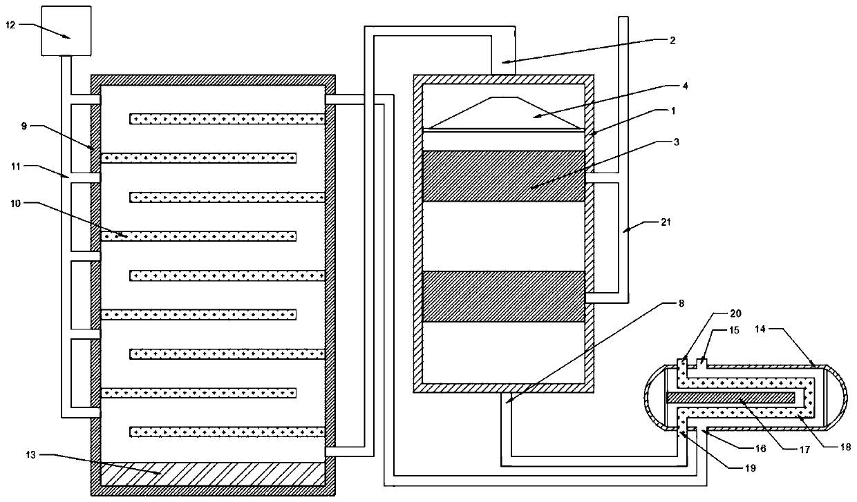
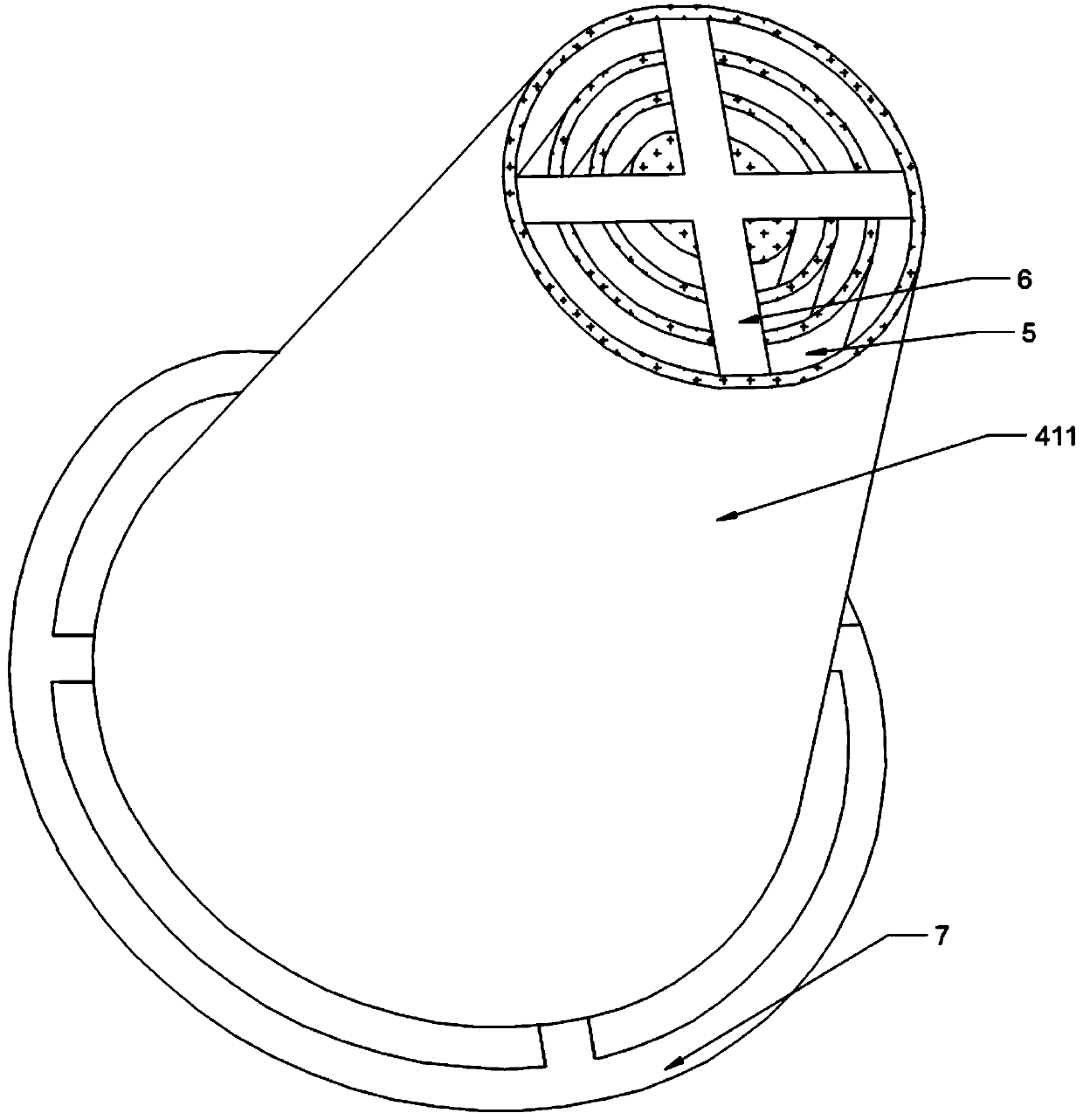
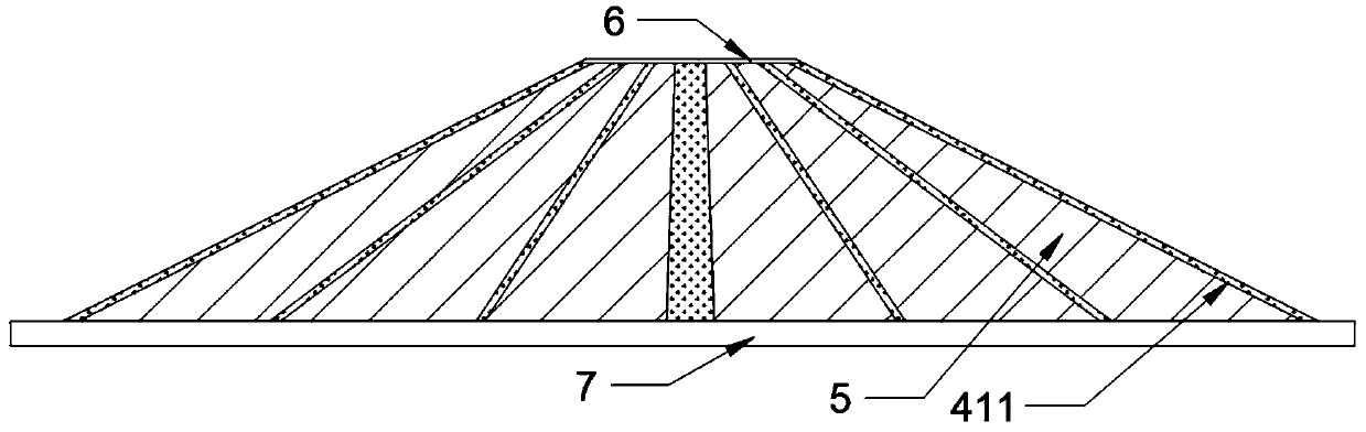
[0022] see Figure 1 to Figure 5 , the present invention provides a production system for rubber fillers, including a reaction tank 1, the top of the reaction tank 1 is provided with a feed pipe 2, crude oil and hydrogen are mixed and heated to reach the reaction temperature and then transported through the feed pipe 2 In the reaction tank 1, several catalyst beds 3 are sequentially arranged in the reaction tank 1 from top to bottom. After crude oil enters the reaction tank 1, it passes through each section of the catalyst bed 3, layer by layer. Carry out hydrogenation reaction, the top of described catalyst bed 3 is provided with diverter mechanism 4, and described diverter mechanism 4 is positioned at the bottom of described feed pipe 2, and described diver...


PUM


Abstract

The invention relates to a production system of rubber filler. The production system of rubber filler comprises a reaction tank, wherein a material inlet pipe is arranged on the top of the reaction tank, a plurality of catalyst bed layers are arranged sequentially in the reaction tank from top to bottom, and a flow dividing mechanism is disposed above the catalyst bed layers; the flow dividing mechanism is arranged right below the material inlet pipe, and includes a plurality of hollow circular truncated cones, the center positions of the circular truncated cones are the same, and the size ofthe circular truncated cones are gradually enlarged from inside out; a bypass passage is formed between every two adjacent circular truncated cones, tops of the circular truncated cones are connectedto each other through upper connecting members, and bottoms of the circular truncated cones are connected to each other through lower connecting members; and a material outlet pipe is arranged on thebottom of the reaction tank. According to the device, flow diversion and buffer of crude oil can be achieved at the same time, the falling speed of the crude oil can also be affected, so that it is ensured that the crude oil is combined with a catalyst timely and evenly for a hydrogenation reaction, and the possibility of coking is reduced greatly.

Description

technical field [0001] The invention relates to the technical field of rubber filler production, in particular to a rubber filler production system. Background technique [0002] As a rubber filler, white oil is more and more widely used in the process of cooperating with rubber. It is an indispensable substance in the rubber industry. The production of white oil is by crude oil normal pressure and vacuum fractionation, solvent extraction and dewaxing. Hydrogenation derived. Hydrofining is an important step in white oil production. By heating the material to a certain temperature and mixing it with hydrogen, the hydrogenation reaction is completed under the action of a catalyst. Hydrofining requires a hydrogenation reactor. The existing hydrogenation The following problems generally exist in the reactor: (1) The hydrogenation process is an exothermic reaction, and the raw material oil is fed from the center of the top of the reactor, and most of them are concentrated in the...

Claims


Application Information

Patent Timeline
Patent Type & Authority Applications(China)
IPC IPC(8): B01J8/02B01J8/04C10G45/02C08L21/00C08L91/06
CPCB01J8/0278B01J8/0446C08L21/00C10G45/02C08L91/06
Inventor 邓桂笔于海彬王国涛吴慧捷
Owner HAINAN HANDI SUNSHINE PETROCHEM
Why Eureka
Try Eureka