Blow molding mold and method equipped with heating stretching system

A technology of blow molding and stretching system, which is applied in glass forming, glass reshaping, glass blowing molds, etc. It can solve the problems of uneven distribution of plastics, easy cracking feet, and difficult pulling of materials, etc., to achieve Effects of reducing weight, enhancing overall strength, and reducing internal stress

Pending Publication Date: 2019-10-08
GUANG DONG XING LIAN PRECISE MACHINERY
View PDF1 Cites 6 Cited by
  • Summary
  • Abstract
  • Description
  • Claims
  • Application Information

AI Technical Summary

Problems solved by technology

However, in the process of use, it was found that since the current stretching rod has no heating system, its temperature is far lower than the temperature of the preform. Cooling in advance will also cause problems such as difficulty in pulling apart some materials, accumulation of material at the bottom, uneven distribution of plastic, easy cracking, and whitening of the bottom feet.

Method used


Image

  • Blow molding mold and method equipped with heating stretching system

Examples


Embodiment 2

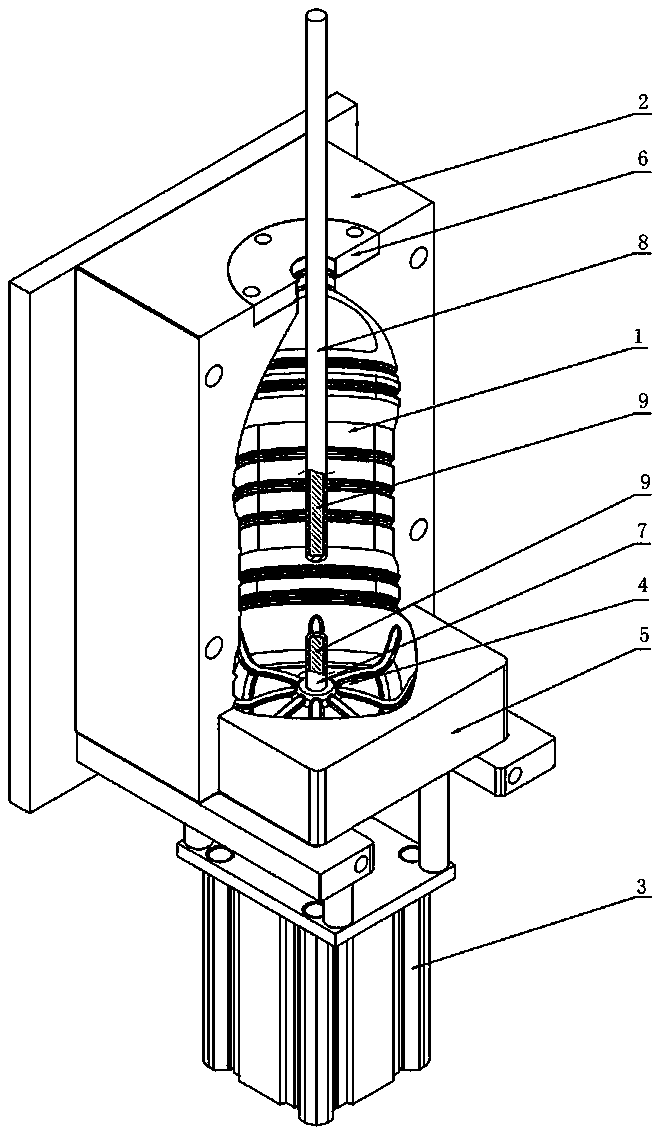
[0031] The method adopted in this embodiment is basically the same as that of Embodiment 1, and the only difference lies in the difference in step 3, which is as follows: when blowing the bottle, first retract the support rod 7 to the lowest position, and pull the stretch rod 8 When stretching the preform to half of the height of 10mm~60mm from the bottom surface of the mold, inject low-pressure air, and pre-blow molding while stretching. After the supporting rod 7 and the stretching rod 8 are in contact, the supporting rod 7 and the stretching rod 8 hold the bottom of the billet and run down to the bottom together, and at the same time, the main blowing high-pressure air makes the preform expand and cling to the inner wall of the mold cavity, Then cool to form a blow-molded container, the above-mentioned height from the bottom surface of the mold is preferably 20 mm to 50 mm, most preferably 40 mm.

Embodiment 3

[0033]The method adopted in this embodiment is basically the same as that of Embodiment 1, except that the difference lies in step 3, which is as follows: when blowing the bottle, first extend the supporting rod 7 by 20 mm to 40 mm, preferably 30 mm, Keeping still, the stretching rod 8 stretches the preform until the pre-blowing air enters, and when it touches the supporting rod 7, it pauses for 0.01s~0.1s, and the preferred pause time is 0.01s~0.3s, so that the preform is in the After being fully stretched under the action of pre-blowing, the supporting rod 7 and the stretching rod 8 together clamp the bottom of the billet and run down to the bottom, and at the same time, the main blowing of high-pressure air makes the preform expand and cling to the inner wall of the mold cavity, It is then cooled to form a blow molded container.

[0034] In the above three embodiments, the pressure of the pre-blowing air is 0.5MPa~1MPa, and the pressure of the main blowing high-pressure air...


PUM


Abstract

The invention discloses a blow molding mold equipped with a heating stretching system. The blow molding mold equipped with the heating stretching system comprises a front mold and a rear mold which form a mold cavity in an encircling mode, a bottom mold located at the bottom of the mold cavity, a bottom mold plate used for installing the bottom mold and a stretching rod stretched from the top of the mold cavity into the mold cavity, wherein a bearing mechanism is arranged in the mold cavity, the bearing mechanism comprises a bearing rod and a drive mechanism which drives the bearing rod to stretch into the middle of the mold cavity, and heating elements are arranged in the stretching rod and / or the bearing rod. According to the blow molding mold equipped with the heating stretching system,the heating elements are arranged in the stretching rod and / or the bearing rod, and when a bottle is blown, temperature of the stretching rod and the bearing rod is approximate to temperature of a bottle blank, situations of early cooling and the like cannot occur, and materials at the bottom of the bottle blank are fully stretched, uniformly distributed at the bottom of the bottle, and cooled and shaped well. Due to the fact that the materials are fully stretched, not only is inner stress at the bottom of the bottle reduced, but also a bursting probability is reduced.

Description

technical field [0001] The invention relates to the technical field of blow molding container molding, in particular to a blow molding mold equipped with a heating and stretching system and a method thereof. Background technique [0002] At present, in the process of blow molding container molding, especially in the two-step blow molding method of injection stretch blowing, the axial stretching of the preform basically touches the inner bottom of the preform through a stretch rod (round steel rod) Stretch the preform to the bottom of the cavity in one go. During the stretching process of the stretch rod, compressed air is injected at the same time, and the preform is inflated with the help of compressed air to make it cling to the cavity wall of the mold, and the hollow plastic product is obtained after cooling and shaping. When the preform is stretched to contact with the metal at the bottom of the mold cavity, the bottom of the preform cools faster, and it is difficult fo...

Claims


Application Information

Patent Timeline
Patent Type & Authority Applications(China)
IPC IPC(8): B29C49/16B29C49/48C03B23/047C03B23/07C03B9/347C03B9/36C03B9/40B29L22/00
CPCB29C49/16B29C49/48B29L2031/7158C03B9/347C03B9/36C03B9/40C03B23/047C03B23/07
Inventor 谢国基姜晓平梁炎均卢佳
Owner GUANG DONG XING LIAN PRECISE MACHINERY
Why Eureka
Try Eureka