
Deposition chamber for improving gas distribution and MPCVD device

A gas distribution and deposition chamber technology, applied in gaseous chemical plating, metal material coating process, coating, etc., can solve problems such as uneven gas distribution, insufficient gas reaction, and affecting the reaction efficiency of chemical vapor deposition devices. Achieve the effect of improving utilization rate and simplifying structure

Active Publication Date: 2019-10-08
ZHENGZHOU RES INST FOR ABRASIVES & GRINDING CO LTD +1
View PDF22 Cites 0 Cited by
  • Summary
  • Abstract
  • Description
  • Claims
  • Application Information

AI Technical Summary

Problems solved by technology

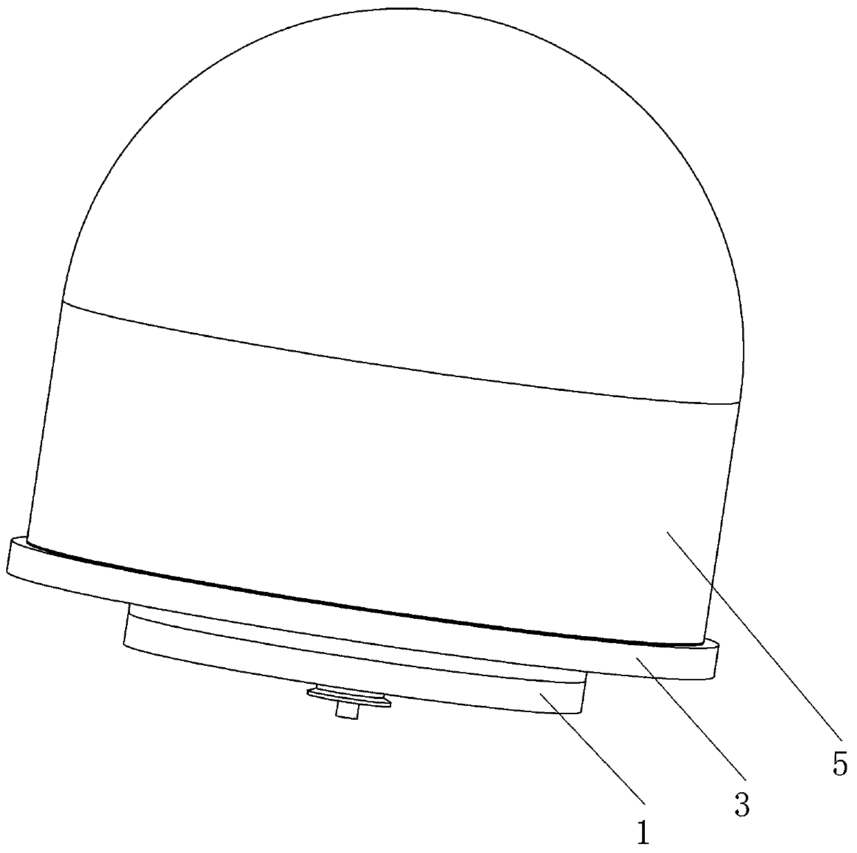
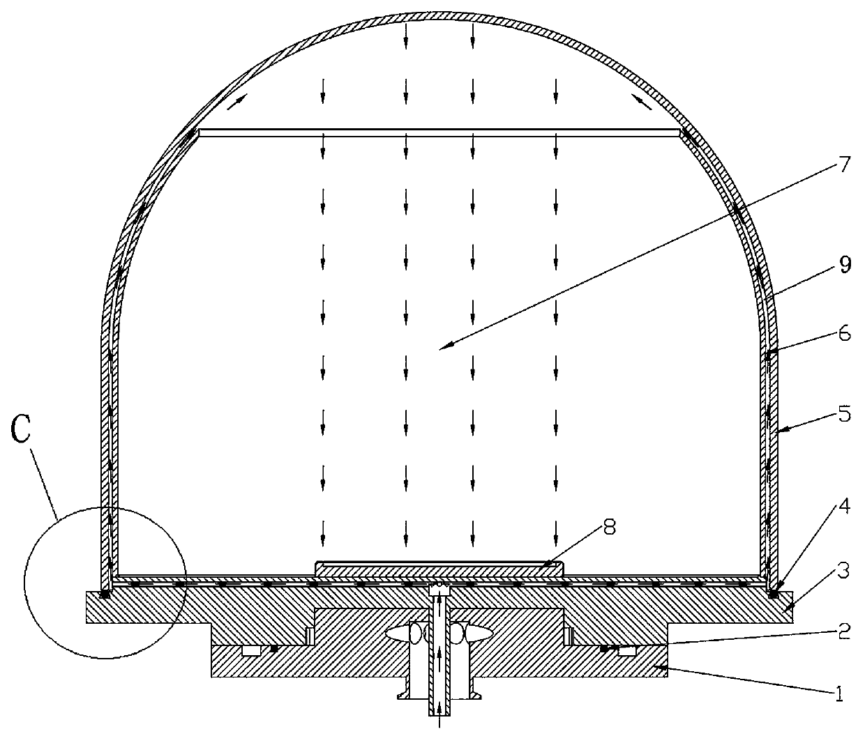
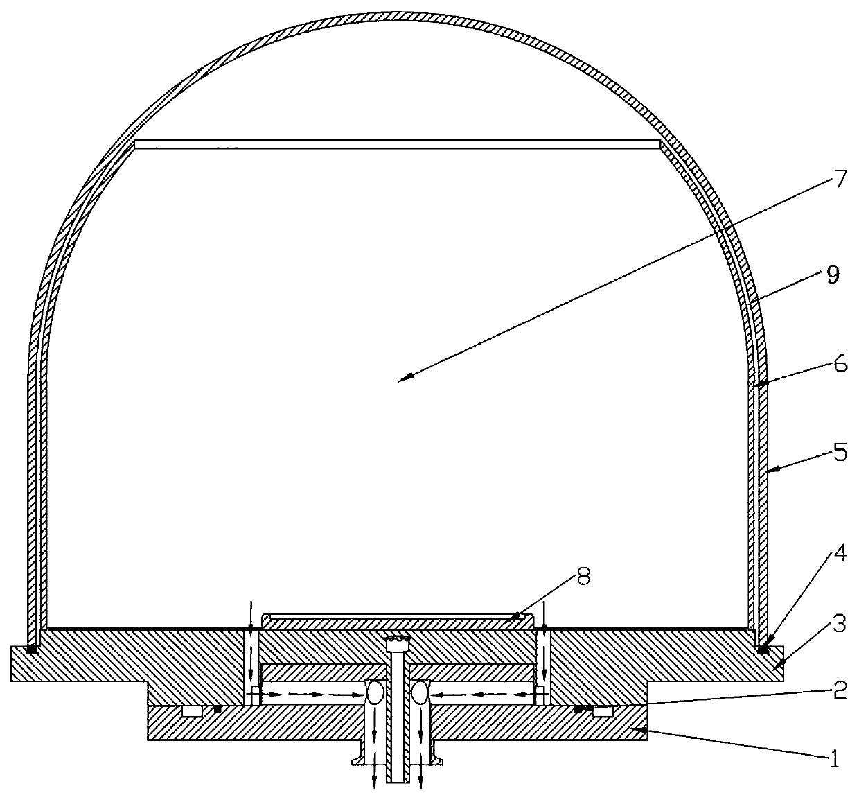
[0004] The purpose of the present invention is to provide a deposition chamber with improved gas distribution, so as to solve the problem that the gas inlet and outlet of the deposition chamber are all arranged on the bottom plate in the prior art, which causes uneven distribution of gas on the surface of the base platform of the deposition chamber
The object of the present invention is also to provide a kind of MPCVD device, to solve the problem that the gas inlet and the gas outlet of the deposition chamber of the chemical vapor deposition device in the prior art are all arranged on the base plate, and the gas cannot fully react in the deposition chamber and affect the entire chemical vapor phase. Technical Problems of Reaction Efficiency of Deposition Device

Method used


Image

  • Deposition chamber for improving gas distribution and MPCVD device
  • Deposition chamber for improving gas distribution and MPCVD device
  • Deposition chamber for improving gas distribution and MPCVD device

Examples


Embodiment Construction

[0054] Embodiment 1 of the deposition chamber for improving gas distribution in the present invention, the deposition chamber in this embodiment is applied in a microwave plasma chemical vapor deposition device.

[0055] In order to facilitate the description of the structure and function of the deposition chamber, the structure of the microwave plasma chemical vapor deposition device is briefly introduced first. A microwave plasma chemical vapor deposition device, that is, an MPCVD device, includes a microwave power supply, a microwave generator, a circulator, a water load, a matcher, a mode converter, and a resonant cavity. A deposition chamber for improving gas distribution is arranged in the resonant cavity. Among them, the microwave generator is used to generate microwaves, which enter the reaction chamber of the deposition chamber after being converted by the mode converter, ionize the gas molecules in the reaction chamber to generate plasma, and react on the correspondin...


PUM


Abstract

The invention belongs to the technical field of microwave plasma chemical vapor deposition, and particularly relates to a deposition chamber for improving gas distribution and an MPCVD device. The deposition chamber comprises a base part, an outer cover body and a deposition table, wherein the outer cover body is hermetically mounted on the base part so as to form a reaction cavity with the base part; the deposition table is arranged on the side, facing the reaction cavity, of the base part, and the base part is provided with an gas inlet channel and an exhaust channel which both communicate with the reaction cavity; the deposition chamber for improving the gas distribution further comprises an air guide channel which is located on the inner side of the outer cover body and extends towardsthe upper part of the reaction cavity, the air guide channel is in butt joint communication with the gas inlet channel, the upper part of the air guide channel communicates with the reaction cavity so as to guide gas input by the gas inlet channel to the upper part of the reaction cavity. The gas guide channel guides upwards the gas entering the deposition chamber, so that the gas can pass through the deposition station before being discharged from the exhaust channel, the utilization rate of the gas is improved, and the reaction efficiency of a deposition device is improved at the same time.

Description

technical field [0001] The invention belongs to the technical field of microwave plasma chemical vapor deposition, and in particular relates to a deposition chamber and an MPCVD device for improving gas distribution. Background technique [0002] Microwave plasma chemical vapor deposition (MPCVD for short) is to use the microwave generated by the microwave generator to enter the deposition chamber through the isolator through the isolator, and to excite the ionization of gas molecules in the deposition chamber to generate plasma, so that in the deposition chamber The process technology in which the surface of the medium substrate reacts and generates a thin film of solid matter, and then deposits the solid material. [0003] For example, the Chinese invention patent with the authorized announcement number CN106987827B discloses a plasma chemical vapor deposition microwave resonant cavity and device. The deposition chamber of the device is surrounded by a frequency tuning pla...

Claims


Application Information

Patent Timeline
Patent Type & Authority Applications(China)
IPC IPC(8): C23C16/517C23C16/455
CPCC23C16/517C23C16/45561C23C16/45591Y02P70/50
Inventor 闫宁吴啸范波常豪锋
Owner ZHENGZHOU RES INST FOR ABRASIVES & GRINDING CO LTD
Learn More