
Multi-laser light spot position detecting device and method based on linear array CCD and FPGA

A detection device and detection method technology, applied in the direction of measuring device, radio wave measuring system, measuring distance, etc., to achieve the effect of improving automation, high precision and reducing error

Pending Publication Date: 2019-10-08
NANJING UNIV OF SCI & TECH
View PDF4 Cites 2 Cited by
  • Summary
  • Abstract
  • Description
  • Claims
  • Application Information

AI Technical Summary

Problems solved by technology

This method is beyond reproach, but if it is applied to the field of surface shape detection, there will be problems. The position detection error brought by it will affect the surface shape detection result

Method used


Image

  • Multi-laser light spot position detecting device and method based on linear array CCD and FPGA
  • Multi-laser light spot position detecting device and method based on linear array CCD and FPGA
  • Multi-laser light spot position detecting device and method based on linear array CCD and FPGA

Examples


Embodiment Construction

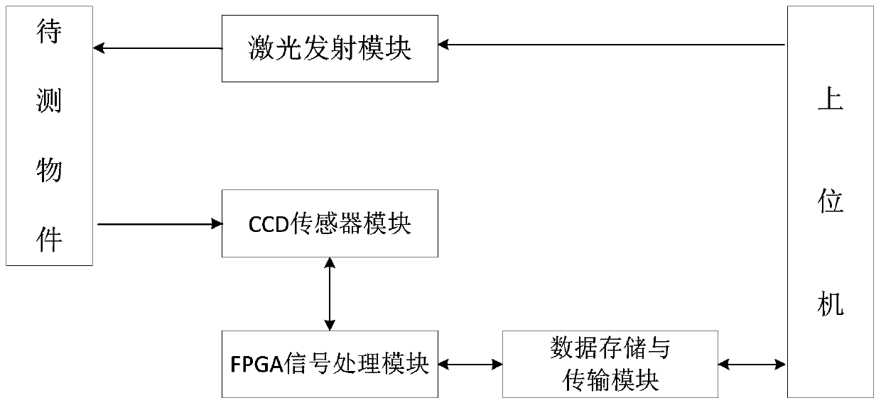
[0023] combine figure 1 , the present invention is based on linear array CCD and FPGA multi-laser spot position detecting device, comprises laser emission module, CCD sensor module, FPGA signal processing module, data storage and transmission module and host computer;

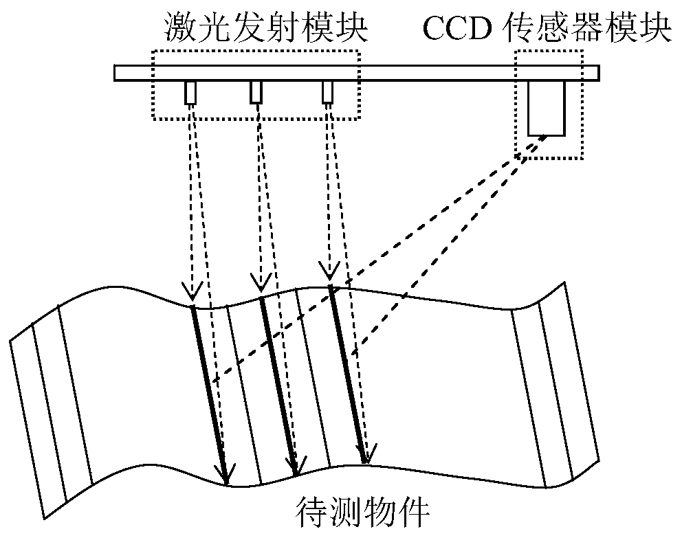
[0024] The laser emitting module is used to vertically emit multi-beam line lasers to the surface of the object to be measured;

[0025] The CCD sensor module is used to receive the laser light reflected by the object to be measured, and perform photoelectric conversion to complete the collection and conversion of optical signals;

[0026] FPGA signal processing module, used for preprocessing and analog-to-digital conversion of analog electrical signals after photoelectric conversion, and realizing multi-laser spot center positioning;

[0027] The data storage and transmission module is used to store the image data of the FPGA signal processing module, and transmit the center positioning results of multiple la...


PUM


Abstract

The invention discloses a multi-laser light spot position detecting device and method based on a linear array CCD and an FPGA. The device comprises a laser emitting module, a CCD sensor module, an FPGA signal processing module, a data storage and transmission module and a host computer. The method comprises the following steps that: the laser emitting module vertically emits a plurality of laser beams to the surface of a to-be-tested piece; the CCD sensor module collects laser reflected by the to-be-tested piece and carries out photoelectric conversion; the FPGA signal processing module performs amplification and analog-to-digital conversion on an analog electrical signal, carries out positioning of centers of multiple laser light spots, and transmits the processed data to the data storageand transmission module and the host computer; and the host computer calculates position information corresponding to each light spot by using a laser triangulation method according to the positioning result, geometric information of the to-be-tested piece is obtained, and a result is outputted. The multi-laser light spot position detecting device and method have advantages of non-contact effect,high sensitivity, high precision, good real-time performance nd high degree of automation and the like; the requirements of industrial production can be met; and the cost is low and the structure issimple. The multi-laser light spot position detecting device and method has the broad application prospects.

Description

technical field [0001] The invention belongs to the technical field of photoelectric measurement, in particular to a multi-laser spot position detection device and method based on a linear array CCD and FPGA. Background technique [0002] Position detection is of great significance in many industrial technical fields such as thickness measurement, width measurement and surface shape detection. Traditional position detection methods include manual measurement, mechanical measurement, etc. These methods have low measurement efficiency, low precision, and cannot be real-time. Measurement, and some measurement methods are in direct contact with the measured object, which will cause secondary damage to the measured object. These methods are no longer suitable for modern industrial production. [0003] With the development of photoelectric technology and mechanical electronics, the position detection technology based on laser triangulation has been gradually applied. The photoele...

Claims


Application Information

Patent Timeline
Patent Type & Authority Applications(China)
IPC IPC(8): G01S17/48G01S7/486G01S7/491G01S7/481
CPCG01S17/48G01S7/4861G01S7/4913G01S7/481
Inventor 陈文建李自奇李武森贺龙龙
Owner NANJING UNIV OF SCI & TECH
Learn More